Construction method of equipment system concept model

A technology of conceptual model and construction method, applied in the field of construction of conceptual model of equipment system, to achieve the effect of improving design efficiency, ensuring completeness and consistency, and ensuring rationality and effectiveness

Inactive Publication Date: 2019-08-16
SHANGHAI INST OF ELECTROMECHANICAL ENG
View PDF3 Cites 1 Cited by
  • Summary
  • Abstract
  • Description
  • Claims
  • Application Information

AI Technical Summary

Problems solved by technology

At present, the research on conceptual design methods is mainly oriented to the conceptual design of a single equipment system, such as: the conceptual design method based on "function-behavior-structure" (the paper "Research on the Conceptual Design of Mechanical Equipment Based on FBS and Elementary Models" by Lu Manze et al., "Mechanical Design" 2018 No. 5), Conceptual Design Method Based on Axiomatic Design Theory (Huang Binda et al.'s paper "Conceptual Design of Machining Fixtures Based on Axiomatic Design Theory", "Combined Machine Tool and Automatic Processing Technology" 2017 No. 2 ), the conceptual design method based on "product-function-structure" (Gong Lin et al.'s paper "Product Conceptual Design Method Integrating Design Process and Design Knowledge", "Computer Integrated Manufacturing System" 2016 No. 3), etc., but for There are few studies on the conceptual design and modeling methods of the equipment system composed of multi-type / multiple different functions and independently operating equipment. The existing research is mainly oriented to the design and modeling of the equipment system in the military field, such as: Design method ("SysML-based model-driven weaponry and equipment architecture design and analysis" by Lu Fa et al., "Command Control and Simulation" No. 1, 2017; "Model-driven weaponry and equipment architecture design" by Li Long et al. , "Journal of Armored Forces Engineering College" 2015 No. 6)

Method used


Image

  • Construction method of equipment system concept model
  • Construction method of equipment system concept model
  • Construction method of equipment system concept model

Examples


Embodiment approach

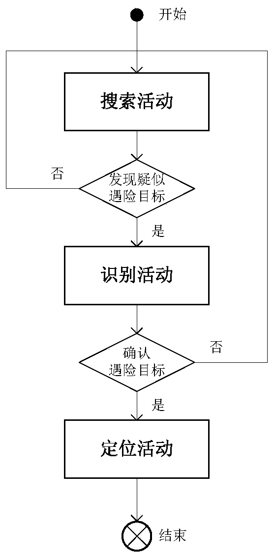
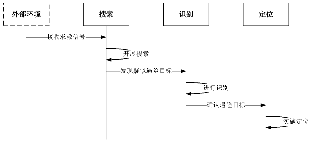
[0040] This implementation mode relates to a sea-air search equipment system that supports maritime search and rescue operations. The mission of the sea-air search equipment system is to dispatch sea rescuers and rescue facilities to search and determine when a ship or people on board are in distress and obtain information about the danger. The location of ships and / or personnel in distress, providing location guidance for subsequent maritime rescue operations.

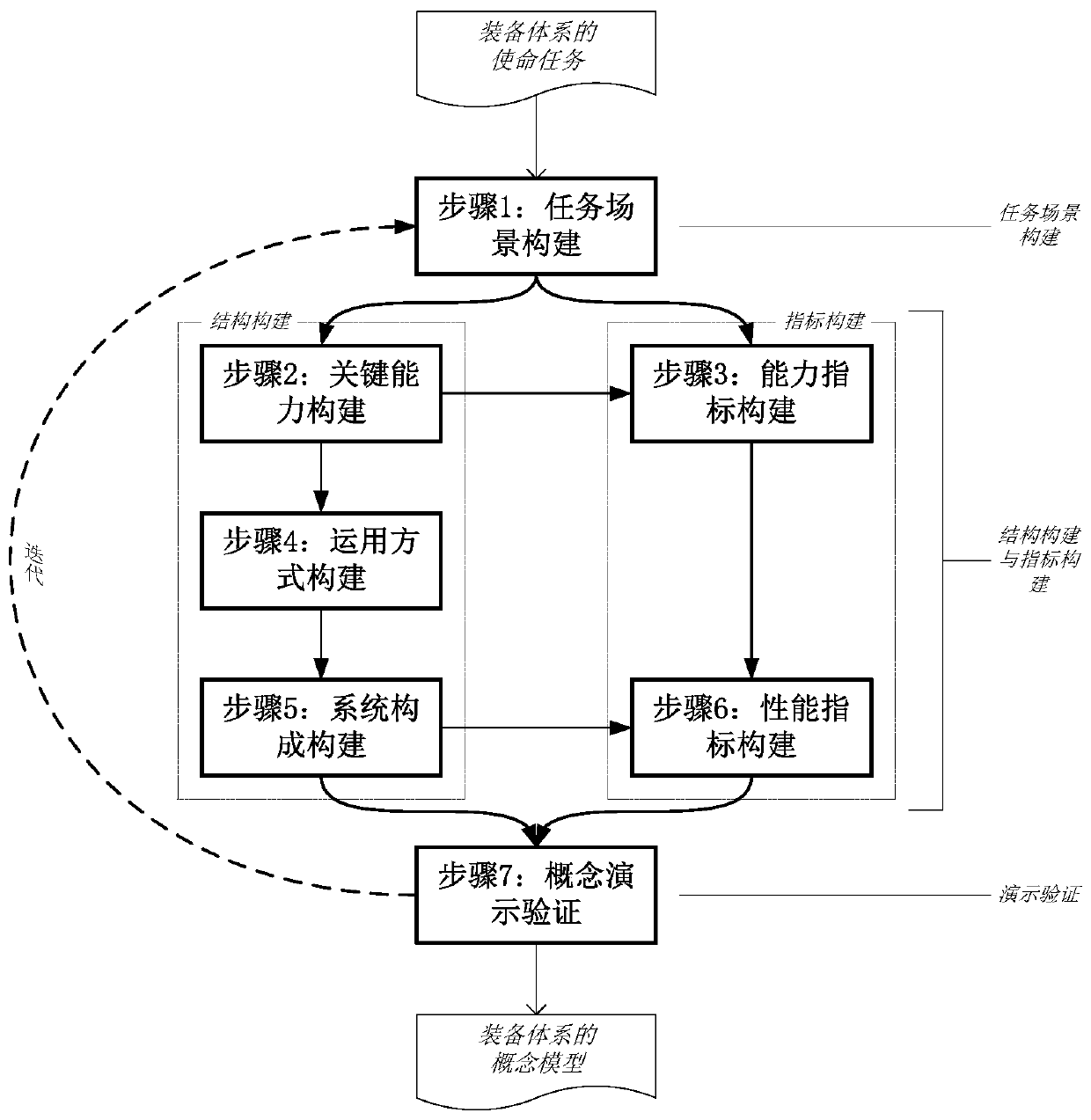
[0041] combine figure 1 , the specific description of the embodiment of the present invention is as follows:

[0042] Step 1: Construction of mission scenarios. Conceive the mission scenarios of the equipment system according to the mission tasks of the equipment system. According to the mission tasks of the sea-air search equipment system, the task scenarios of the sea-air search equipment system are conceived as follows:

[0043] Table 1 Mission Scenarios of Sea and Air Search Equipment System

[0044]

[0045...


PUM


Abstract

The invention provides a construction method of an equipment system concept model. The construction method of the equipment system concept model comprises the following steps: a task scene construction step; a key capability construction step; a capability index construction step; an application mode construction step; an equipment construction step; a performance index construction step; and a concept demonstration verification step. According to the method, the correlation mapping relations of task scene, key capability, application mode, and equipment composition; the key capability and the capability index; the equipment composition and the performance index; and the capability index and the performance index are established, and through the correlation mapping relations, completenessand consistency of the conceptual model in the construction process of the conceptual model of the equipment system are better guaranteed.

Description

technical field [0001] The invention relates to the field of conceptual design and modeling, in particular to a method for constructing a conceptual model of an equipment system. Background technique [0002] Conceptual design is an important stage of product design. Conceptual design is the stage where the designer already has a preliminary design plan in his mind, but has not yet formed a specific plan. to describe. At present, the research on conceptual design methods is mainly oriented to the conceptual design of a single equipment system, such as: the conceptual design method based on "function-behavior-structure" (the paper "Research on the Conceptual Design of Mechanical Equipment Based on FBS and Elementary Models" by Lu Manze et al., "Mechanical Design" 2018 No. 5), Conceptual Design Method Based on Axiomatic Design Theory (Huang Binda et al.'s paper "Conceptual Design of Machining Fixtures Based on Axiomatic Design Theory", "Combined Machine Tool and Automatic Pr...

Claims


Application Information

Patent Timeline
Patent Type & Authority Applications(China)
IPC IPC(8): G06F17/50
CPCG06F30/20
Inventor 董晨陆志沣洪泽华钱晓超何舒陆营波章佳君
Owner SHANGHAI INST OF ELECTROMECHANICAL ENG
Why Eureka
Try Eureka