Electron beam fuse wire deposition forming wire end position closed-loop control system and method

A closed-loop control and fuse deposition technology, which is applied in the field of additive manufacturing, can solve the problems of forming interruption, wire sticking, and uneven unevenness, and achieve the effect of improving stability and reliability

Active Publication Date: 2019-08-20
AVIC BEIJING AERONAUTICAL MFG TECH RES INST
View PDF6 Cites 6 Cited by
  • Summary
  • Abstract
  • Description
  • Claims
  • Application Information

AI Technical Summary

Problems solved by technology

[0004] In the process of electron beam fuse deposition forming, as the forming proceeds, the formed part will be deformed and local unevenness will easily appear, the distance between the wire end and the surface of the deposited substrate will change, and when the distance is too large, it will cause large drops Transition, the surface of the deposition body becomes rough and even defects will occur. When the distance is too small, the wire will be forced to slide out of the molten pool, which will easily cause sticking wire, resulting in interruption of forming
At present, the distance between the wire end and the surface of the deposited substrate is observed by human eyes, and then the height of the motion platform or electron gun is manually adjusted to ensure that the distance is at a more appropriate level. However, manual operation is prone to errors, and the accuracy and reliability of the adjustment cannot be guaranteed. open-loop control method

Method used


Image

  • Electron beam fuse wire deposition forming wire end position closed-loop control system and method

Examples


Embodiment Construction

[0022] The embodiments of the present invention will be described in further detail below with reference to the accompanying drawings and examples. The detailed description of the following embodiments and the accompanying drawings are used to exemplify the principles of the present invention, but not to limit the scope of the present invention, that is, the present invention is not limited to the described embodiments without departing from the spirit of the present invention. Any equivalent modifications, substitutions and improvements are covered below.

[0023] It should be noted that the embodiments in the present application and the features of the embodiments may be combined with each other in the case of no conflict. The present application will be described in detail below with reference to the accompanying drawings and in conjunction with the embodiments.

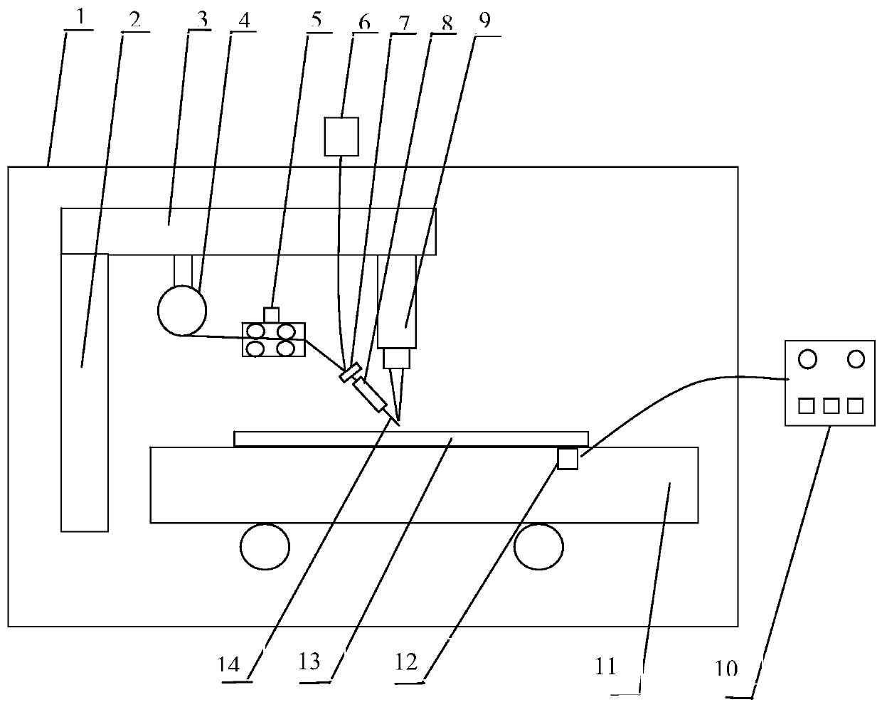
[0024] In the first aspect, the embodiments of the present invention provide figure 1 A closed-loop control s...


PUM


Abstract

The invention relates to an electron beam fuse wire deposition forming wire end position closed-loop control system and method, and belongs to the technical field of additive manufacturing. The systemcomprises a forming vacuum chamber, a wire feeding mechanism and an electron gun. In the forming vacuum chamber, the wire feeding mechanism conveys a metal wire to a conductive substrate through a wire nozzle, and the electron gun transmits electron beams for fuse wire deposition forming. The system and method are characterized in that the wire feeding structure, the wire nozzle and the electrongun are all mounted on a lifting support, the output wire end of the wire is connected with a waveform current generating power source outside the forming vacuum chamber, the conductive substrate is mounted on a movable platform in the forming vacuum chamber, a waveform current receiver is mounted at the bottom of the conductive substrate and used for receiving a current signal between the outputwire end and the conductive substrate, the waveform current receiver is connected with the control system, and the control system is connected with and controls the lifting support and the movable platform to move.

Description

technical field [0001] The invention relates to the technical field of additive manufacturing, in particular to a closed-loop control system and method for the position of an electron beam fuse deposition forming wire end. Background technique [0002] Electron beam fuse forming is an emerging additive manufacturing technology, which is based on the mature high-energy beam surfacing and cladding technology, and integrates rapid prototyping (Rapid Prototyping), computer-aided design and manufacturing (CAD&CAM), The flexible automation technology realizes the near-net-shape direct manufacturing of high-performance and complex-structured dense metal parts, which is a new direction for the development of current advanced manufacturing technology. [0003] This technology is similar to Electron Beam Solid Free Manufacturing (EBSFF) or Electron Beam Free Forming Rapid Manufacturing (EBF3), both of which use a side-axis wire-fed fusion deposition method. NASA's Langley Research Ce...

Claims


Application Information

Patent Timeline
Patent Type & Authority Applications(China)
IPC IPC(8): B23K15/00
CPCB23K15/0086
Inventor 杨光巩水利许海鹰杨帆
Owner AVIC BEIJING AERONAUTICAL MFG TECH RES INST
Why Eureka
Try Eureka