3D bio-printer head control device and material changing control method of head

A bio-printer and control device technology, applied in manufacturing auxiliary devices, processing data acquisition/processing, additive processing, etc., can solve the problems of printing material pollution, blockage, and viscous material accumulation nozzles, etc., to improve printing efficiency, disassembly and assembly. The effect of convenient use and simple device structure

Inactive Publication Date: 2019-08-20
TAIYUAN UNIV OF TECH
View PDF2 Cites 2 Cited by
  • Summary
  • Abstract
  • Description
  • Claims
  • Application Information

AI Technical Summary

Problems solved by technology

[0003] 3D bioprinter is a kind of equipment that can position and assemble biological materials or cell units according to the principle of additive manufacturing under the drive of digital three-dimensional model, and manufacture medical devices, tissue engineering scaffolds, tissues and organs and other products; in actual use, due to biological The viscosity of the material is relatively high, and ordinary industrial piezoelectric nozzles cannot spray biomaterials with a viscosity exceeding 20 cps. After the 3D printer has been used for a period of time, viscous materials are likely to accumulate at the nozzle position and cause nozzle clogging.
[0004] After the nozzle is clogged, in order to keep the printing going, it is neces...

Method used


Image

  • 3D bio-printer head control device and material changing control method of head
  • 3D bio-printer head control device and material changing control method of head
  • 3D bio-printer head control device and material changing control method of head

Examples


Embodiment Construction

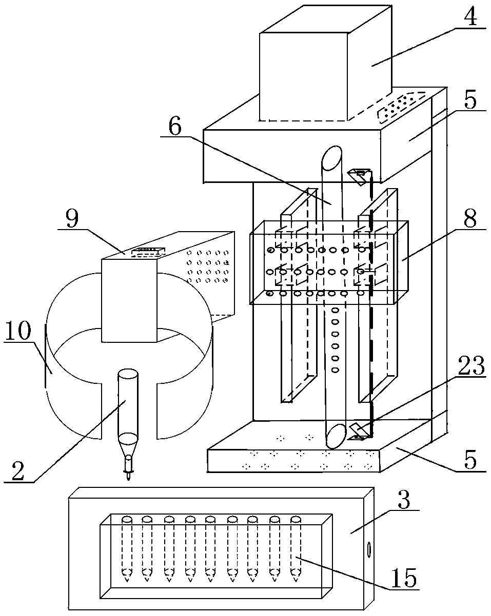
[0035] Such as Figure 1 to Figure 5 As shown, a 3D bioprinter nozzle control device of the present invention includes a motor control frame (1), a printing nozzle (2) and a refueling device (3), and the motor control frame (1) is set on the top of the 3D bioprinter , one side of the motor control frame (1) is provided with a stepping motor (4), and the two ends of the motor control frame (1) are extended outward with fixed beams (5), and the fixed beams (5) A threaded shaft (6) is provided on the top, and the threaded shaft (6) drives the movement of the printing device (7) on the Y-axis printing plane through the stepping motor (4);

[0036] The printing device (7) includes a connecting end (8) and a fixed end (9), the connecting end (8) and the fixed end (9) are fixed by bolts, and the connecting end (8) and the threaded shaft (6 ) transmission connection, the extension end of the fixed end (9) is provided with a fixing clip (10), and the fixing clip (10) is used to clamp ...


PUM


Abstract

The invention relates to a 3D bio-printer head control device and a material changing control method of a head, and belongs to the technical field of 3D bio-printer head control. The technical problemto be solved is to provide a 3D bio-printer head structure, a hardware structure of a control device and improvement of the material changing control method of the head. According to the technical scheme used for solving the technical problem, the device comprises a motor control frame, a printing head and a material changing device, wherein the motor control frame is arranged at the top of the 3D bio-printer, a stepping motor is arranged on one side of the motor control frame, two ends of the motor control frame extend outwards and are provided with fixed beams, a threaded shaft is arrangedon the fixed beams, the threaded shaft drives a printing device to move on the Y-axis printing plane through the stepping motor; and the printing device comprises a connecting end and a fixing end, wherein the connecting end is fixedly connected with the fixing end through a bolt, the connecting end is in transmission connection with the threaded shaft, a fixing clamp is arranged at the extendingend of the fixing end, and the fixing clamp is used for clamping a printing head. The control device is applied to the 3D bio-printer.

Description

technical field [0001] The invention discloses a 3D bioprinter nozzle control device and a nozzle refueling control method, belonging to the technical field of 3D bioprinter nozzle control. Background technique [0002] 3D printing is a kind of rapid prototyping technology. It is a technology based on digital model files and using bonding materials such as powdered metal or plastic to construct objects by layer-by-layer printing. 3D printing technology appeared in the mid-1990s and is actually the latest rapid prototyping device utilizing technologies such as light curing and paper lamination. The working principle of it is basically the same as that of ordinary printing. The printer is filled with "printing materials" such as liquid or powder. After being connected to the computer, the "printing materials" are superimposed layer by layer through computer control, and finally the blueprint on the computer is turned into a real object. [0003] 3D bioprinter is a kind of equ...

Claims


Application Information

Patent Timeline
IPC IPC(8): B29C64/393B33Y50/02
CPCB29C64/393B33Y50/02
Inventor 桑胜波孙建其周传刚张博菅傲群段倩倩张益霞张成然刘伟伟
Owner TAIYUAN UNIV OF TECH
Why Eureka
Try Eureka