Detachable disassembly and assembly cap screwing mechanism of cap screwing machine

A plug-in and capping machine technology, which is applied in the direction of capping containers tightly with caps, packaging, and threaded bottle caps, can solve problems such as bottle breaking, time-consuming, laborious, and damage, and achieve simplified disassembly and processing. The structure is simple and the effect of improving efficiency

Pending Publication Date: 2019-08-20
孙方卓 +1
View PDF0 Cites 7 Cited by
  • Summary
  • Abstract
  • Description
  • Claims
  • Application Information

AI Technical Summary

Problems solved by technology

In the existing capping mechanism, the installation method between the capping jaw parts and the lifting and rotating device is threaded or connected by a screw. The replacement and disassembly of the capping jaw parts are very troublesome, time-consuming and laborious. , and in the existing capping mechanism, there is a hard connection between the capping jaw parts and the lifting and rotating device. If the capping head hits the bottle mouth, the bottle will be broken or deformed, and the capping mechanism will be damaged if it is serious. Impact deformation or damage
In addition, the rubber in the jaws of the existing capping head is glued or fixed with screws, and the rubber cannot be replaced. Even if the rubber can be replaced, it will take time and effort, which is very troublesome

Method used


Image

  • Detachable disassembly and assembly cap screwing mechanism of cap screwing machine
  • Detachable disassembly and assembly cap screwing mechanism of cap screwing machine

Examples


Embodiment

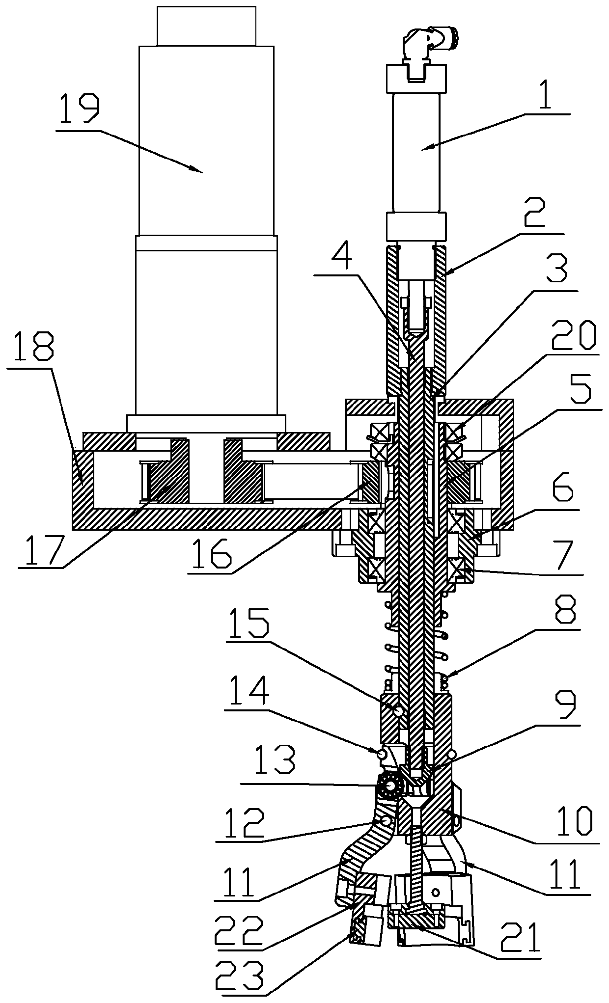
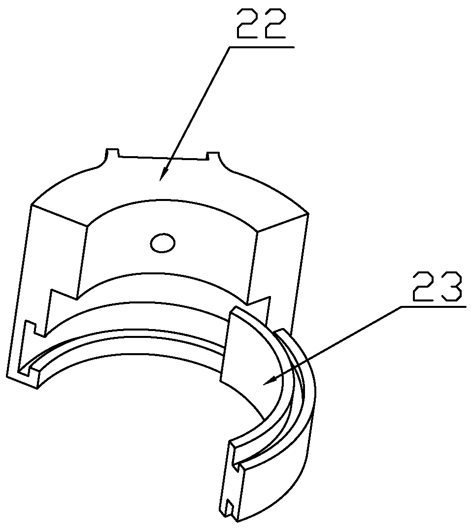
[0019] Embodiment: a plug-in dismounting and capping mechanism of a capping machine, such as figure 1 , figure 2 As shown, it includes lifting cylinder 1, connecting sleeve 2, rotating sleeve shaft 3, joystick 4, supporting shaft 5, bearing seat 6, bearing 7, return spring 8, cone pushing head 9, jaw seat cover 10, jaw Arm 11, revolving pin 12, rolling ring 13, elastic ring 14, axial plug pin 15, driven pulley 16, driving pulley 17, transmission case 18, power head 19, lock nut 20, bottle cap limit The positioning rod 21, the jaw block 22 and the wear-resistant rubber 23, the rotating sleeve shaft 3 and the supporting rotating shaft 5 are connected through a spline coaxial sleeve, the rotating sleeve shaft 3 is located in the supporting rotating shaft 5, and the supporting rotating shaft 5 is distributed through two intervals The bearing 7 and the bearing seat 6 are installed vertically on the transmission box 18, the driven pulley 16 is set on the supporting shaft 5 through...


PUM


Abstract

The invention discloses a detachable disassembly and assembly cap screwing mechanism of a cap screwing machine. According to the detachable disassembly and assembly cap screwing mechanism of the cap screwing machine, a cap clamping device and a supporting rotary shaft can be assembled and disassembled quickly and conveniently through an axial plug pin. A clamping claw block is detachably installedon the inner side of the lower end of a clamping claw arm. Wear-resistant rubber is arranged on the inner side of the clamping claw block. In the process of clamping a cap and screwing the cap, if the clamping claw arm bumps the bottle cap accidently, the clamping claw arm will be pushed to move upwards, and a power head is controlled to lose power and stop rotating through an infrared travel switch; when the bottle cap dimensions need to be changed, a clamping claw base sleeve can be quickly and conveniently detached just by pulling out the axial plug pin, and in other words, the cap clamping device can be easily and conveniently detached and replaced; and because the clamping claw block and the wear-resistant rubber are of a plug-in structure according to designing, replacement and processing can be conveniently carried out, and assembly, disassembly and processing can be carried out on the cap clamping device much more easier. No tools are needed for replacing the cap clamping device, quickness and convenience are achieved; and when the rubber in the clamping claw block needs to be replaced, it is only needed that a rubber strip is directly inserted into a T-shaped groove of the clamping claw block, no tools or glue is needed, the designing is exquisite, simpleness and practicability are achieved, the operation of workers is facilitated to a great extent, and the efficiencyis improved.

Description

technical field [0001] The invention relates to the technical field of capping machines, in particular to a capping and capping mechanism of a capping machine. Background technique [0002] The capping machine is equipped with a capping mechanism. The capping mechanism is installed on the lifting and rotating device of the capping machine. Put it on the top of the bottle and screw it on. In the existing capping mechanism, the installation method between the capping jaw parts and the lifting and rotating device is threaded or connected by a screw. The replacement and disassembly of the capping jaw parts are very troublesome, time-consuming and laborious. , and in the existing capping mechanism, there is a hard connection between the capping jaw parts and the lifting and rotating device. If the capping head hits the bottle mouth, the bottle will be broken or deformed, and the capping mechanism will be damaged if it is serious. Deformed or damaged by impact. In addition, the...

Claims


Application Information

Patent Timeline
Patent Type & Authority Applications(China)
IPC IPC(8): B67B3/20
CPCB67B3/2066
Inventor 孙方卓陈慧
Owner 孙方卓
Why Eureka
Try Eureka