
Active phased array system test method and test bench

A system test and phased array technology, applied to radio wave measurement systems, instruments, etc., to achieve a wide range of hardware interfaces, facilitate test work, and improve the scope of application

Active Publication Date: 2019-08-20
CHINA ELECTRONIC TECH GRP CORP NO 38 RES INST
View PDF10 Cites 4 Cited by
  • Summary
  • Abstract
  • Description
  • Claims
  • Application Information

AI Technical Summary

Problems solved by technology

[0003] At this stage, the design of the test bench is aimed at a fixed type of active phased array system, so the current test bench can only support a fixed model and a fixed number of components to be tested, which leads to the need to use different types of tests for different types of product tests bench for repeated test bench software and hardware development

Method used


Image

  • Active phased array system test method and test bench
  • Active phased array system test method and test bench
  • Active phased array system test method and test bench

Examples


Embodiment 1

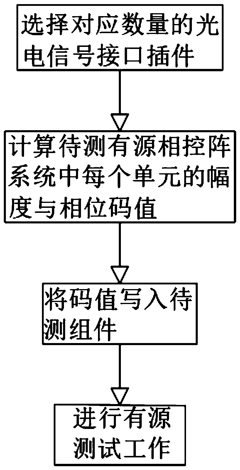
[0053] Such as figure 1 As shown, the present embodiment provides a method for testing an active phased array system, comprising the following steps:

[0054] S1: Select the corresponding number of photoelectric signal interface plug-ins

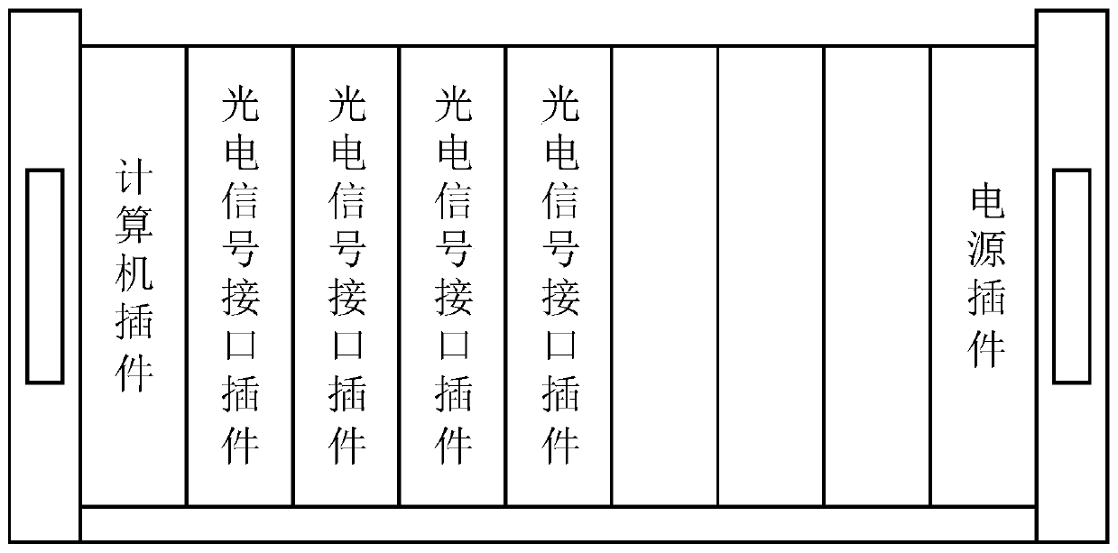
[0055] According to the scale of the active phased array system to be tested, install a corresponding number of photoelectric signal interface plug-ins in the CPCI computer case, and assign bus addresses and corresponding control objects to the photoelectric signal interface plug-ins;

[0056] S2: Calculate the amplitude and phase code value of each unit in the active phased array system to be tested

[0057] Use the computer plug-in to calculate the amplitude and phase code value of each unit in the active phased array system to be tested, and write the code value data into the corresponding PCI bus address according to the address list;

[0058] S3: Write the code value into the component under test

[0059] Read the code value list fro...

Embodiment 2

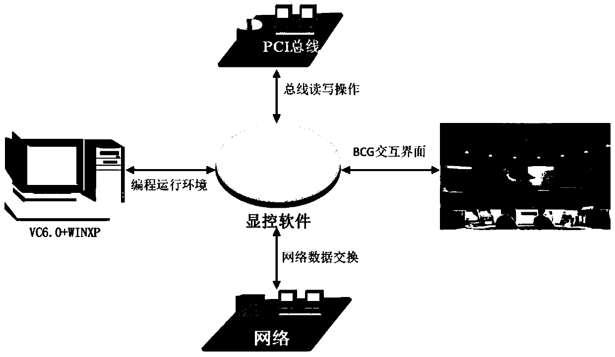
[0087] Such as image 3 As shown, the display control software runs in the computer plug-in of the test bench, figure 2 It shows some characteristics of the display control software, uses BCGControl plug-in to write user interface, has PCI bus data reading and writing functions, has network communication functions, and runs under WINXP operating system.

[0088] Such as Figure 4 As shown, it is a diagram of the connection mode between the test bench and the active phased array system to be tested. In the figure, the test bench is connected to the active components in the active phased array system to be tested through the hardware interface of the photoelectric signal interface plug-in. The photoelectric signal interface plug-in and the computer plug-in exchange test data through the PCI bus, and the working timing between the photoelectric signal interface plug-ins is synchronized through the bus. The test bench receives the trigger signal from the near-field test system ...


PUM


Abstract

The invention discloses an active phased array system test method and a test bench, belonging to the technical field of active phased array radar test. The test bench comprises a CPCI computer chassisfor mounting a test bench assembly, a computer plug-in for calculating amplitude and phase code values of each unit in a to-be-tested active phased array system, multiple photoelectric signal interface plug-ins for configuring input or output interfaces and a power supply module as a power supply. The number of plug-ins can be selected according to a different test item scale to test the active phased array system, the photoelectric signal interface plug-ins have wide hardware interface types, the interfaces are multiple, and the advantages of scalable test scale and good test assembly compatibility are achieved; and timing synchronization is maintained with a near-field test system through the photoelectric signal interface plug-ins, the active phased array systems for different models of products can be tested more conveniently, and promotion and use are worthwhile.

Description

technical field [0001] The invention relates to the technical field of active phased array radar testing, in particular to an active phased array system testing method and a test bench. Background technique [0002] The near-field test of the active phased array system is an important part of the research and development of the active phased array radar (AESA). The near-field test of the system is mainly to control the active phased array system under test to complete the electrical performance indicators of the system under test test. In order to improve the test efficiency of the active phased array system, a test bench is usually used to control the active phased array to complete the work. [0003] At this stage, the design of the test bench is aimed at a fixed type of active phased array system, so the current test bench can only support a fixed model and a fixed number of components to be tested, which leads to the need to use different types of tests for different ty...

Claims


Application Information

Patent Timeline
Patent Type & Authority Applications(China)
IPC IPC(8): G01S7/40
CPCG01S7/4004
Inventor 张重阳张卿陈旭黄文涛张再庆钱林夏艳
Owner CHINA ELECTRONIC TECH GRP CORP NO 38 RES INST
Learn More