
a display device

A display device and display panel technology, applied in instruments, optics, nonlinear optics, etc., can solve the problems of high light loss, reduced brightness and contrast of display products, and light color in the middle area of ​​the panel, so as to reduce useless light and reduce light. Loss, increases the effect of useful light

Active Publication Date: 2022-04-19
BOE TECH GRP CO LTD +1
View PDF6 Cites 0 Cited by
  • Summary
  • Abstract
  • Description
  • Claims
  • Application Information

AI Technical Summary

Problems solved by technology

[0003] In the existing PNLC transparent display products, after the light emitted by the light source enters the panel, most of the light directly enters the human eye without passing through the liquid crystal or exits from the side of the panel, resulting in more light loss and reducing the brightness and contrast of the display product. For large size transparent display panels, there is also a serious problem of lighter color in the middle area of ​​the panel

Method used


Image

  • a display device
  • a display device
  • a display device

Examples


no. 1 example

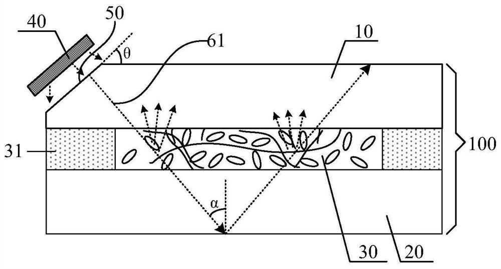
[0036] figure 2 It is a schematic structural diagram of the display device according to the first embodiment of the present invention. Such as figure 2 As shown, the display device includes a display panel 100 and a light source 40 . The display panel 100 is provided with a light incident surface 50 on a side thereof, and the light incident surface 50 is inclined relative to the plane where the display panel 100 is located. The light source 40 is disposed on the light incident surface 50 , and the light emitted by the light source 40 enters the display panel 100 from the light incident surface 50 .

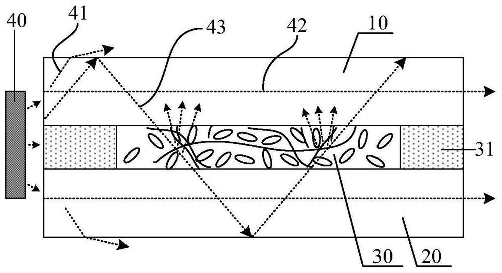
[0037] By analyzing as figure 1 It can be seen from the structure of the display device shown that since the light source 40 is arranged on the side of the display panel, most of the light emitted by the light source 40 will be transmitted in the direction of the first path 41 and the second path 42 in the display panel without passing through the liquid crystal. layer, resu...

no. 2 example

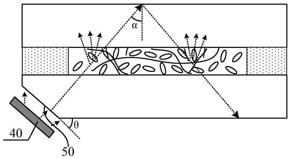
[0046] Figure 4 It is a schematic structural diagram of a display device according to the second embodiment of the present invention. Different from the first embodiment, in the second embodiment of the present invention, as Figure 4 As shown, the light incident surface 50 includes a first light incident surface 51 disposed on the side of the first substrate 10 and a second light incident surface 52 disposed on the side of the second substrate 20 . The light emitted from the light source 40 respectively enters the display panel 100 from the first light incident surface 51 and the second light incident surface 52 .

[0047] The included angle θ1 between the first light incident surface 51 and the plane of the first substrate 10 is greater than or equal to 41°, and the included angle θ2 between the second light incident surface 52 and the plane of the second substrate 20 is greater than or equal to 41°.

[0048] In one embodiment, the first light incident surface 51 is arran...


PUM

PropertyMeasurementUnit
angleaaaaaaaaaa

Abstract

The invention discloses a display device. The display device includes a display panel and a light source, the display panel is provided with a light incident surface inclined relative to the plane where the display panel is located on the side, and the light emitted by the light source enters the display panel from the light incident surface middle. In the display device of the embodiment of the present invention, the light emitted by the light source enters the display panel from the light incident surface inclined relative to the plane where the display panel is located, increasing the light in the display panel that passes through the liquid crystal scattering state, and these light rays pass through the liquid crystal scattering state. Scattered light will be generated, light loss is reduced, useful light is increased, useless light is reduced, the utilization rate of the light source is increased, and the brightness and contrast of the display device are improved.

Description

technical field [0001] The present invention relates to the field of display technology, in particular to a display device. Background technique [0002] With the development of science and technology, the application of transparent display in smart homes, wearables, and vehicles is becoming more and more extensive. In the prior art, transparent display mainly includes liquid crystal display (LCD) transparent display products, organic light emitting diode (OLED) transparent display products, and the like. Due to the light-absorbing effect of polarizers in LCD transparent display products, the transmittance of LCD transparent display products is lower than 20%, which cannot meet customer needs. The cost of OLED transparent display products is high, and the transmittance is about 40%. Polymer Network Liguid Crystal (PNLC) transparent display products use the scattered light intensity of the incident light on the side after the liquid crystal is powered on to realize the disp...

Claims


Application Information

Patent Timeline
Patent Type & Authority Patents(China)
IPC IPC(8): G02F1/1334G02F1/13357
CPCG02F1/1334G02F1/133615G02F1/13345
Inventor 毕谣袁洪亮武晓娟陈会顺郑琪赵志强钟璇程张祥张冬华王家星郭兰军
Owner BOE TECH GRP CO LTD
Learn More