Eureka AIR delivers breakthrough ideas for toughest innovation challenges, trusted by R&D personnel around the world.

A Power Transistor Gate Drive Circuit with Segment Drive Function

A gate drive circuit and segmental drive technology, which is applied in the direction of output power conversion device, DC power input conversion to DC power output, electrical components, etc., can solve the problem of high gate charging current, difficult implementation, and segmental drive Complex structure and other issues, to achieve the effect of reducing circuit complexity and simple implementation

Active Publication Date: 2020-11-27
UNIV OF ELECTRONICS SCI & TECH OF CHINA
View PDF6 Cites 0 Cited by
  • Summary
  • Abstract
  • Description
  • Claims
  • Application Information

AI Technical Summary

Problems solved by technology

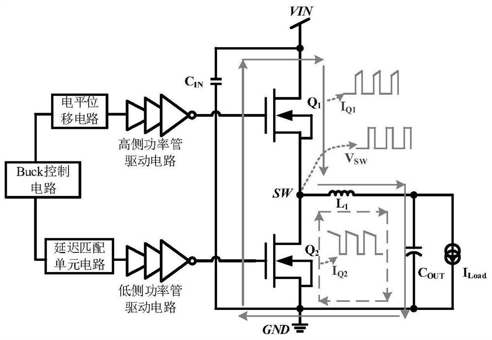
[0005] Aiming at the EMI problem of the DC-DC converter due to the high gate charging current during the turn-on process of the power tube, as well as the shortcomings of the traditional segmented drive structure, which is difficult to implement, the present invention proposes a segmented drive function The gate drive circuit can be used to drive high-side power tubes and low-side power tubes in DC-DC converters. It adopts a segmented drive strategy and uses the gate charging current control technology (RGCC: Regulation of Gate Charging Current) to stage Regulate the gate charging current during the turn-on process of the power tube, realize the dv / dt slope of the switch node voltage change of the DC-DC converter, and optimize the di / dt slope of the power loop current change, and realize the purpose of optimizing the EMI of the DC-DC converter

Method used


Image

  • A Power Transistor Gate Drive Circuit with Segment Drive Function
  • A Power Transistor Gate Drive Circuit with Segment Drive Function
  • A Power Transistor Gate Drive Circuit with Segment Drive Function

Examples


Embodiment Construction

[0041] The specific implementation manner and principle of the present invention will be further elaborated below in conjunction with the drawings.

[0042] The present invention proposes a gate drive circuit for driving N-type power tubes, which is suitable for DC-DC converters and can be used to drive high-side power tubes or low-side power tubes of DC-DC converters. When the power tube is used, the power rail of the gate drive circuit is the high-side floating power rail (BST-SW) of the DC-DC converter, and the relatively high level of the high-side floating power rail is the floating power supply BST of the DC-DC converter. The relatively low level of the side floating power rail is the level at the switch node SW of the DC-DC converter; when driving the low-side power tube, the power rail of the gate drive circuit is the low-side power rail of the DC-DC converter ( VDD-GND), the relatively high level of the low-side floating power supply rail is the internal low-voltage p...


PUM


Abstract

The utility model relates to a grid drive circuit of a power tube with segment drive function, which belongs to the technical field of power management. Including the main control module, short pulse generation module and feedback clamping module, the main control module includes traditional inverter drive chain, power tube on and off circuit, used to control the power tube; short pulse generation module is used for grid voltage detection and Segment switching control, the pulse time is the positive short pulse signal and the negative short pulse signal when the power tube grid voltage rises from zero to the segment voltage; the feedback clamp module is used to control the charging current of the power tube grid, in the short pulse stage The feedback clamping module can provide small current charging for the power tube grid, and provide high current charging for the power tube grid after the short pulse to realize segmented driving. The invention is suitable for DC-DC converters, can balance high efficiency and EMI optimization of DC-DC converters, and has a simple implementation method.

Description

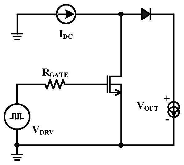
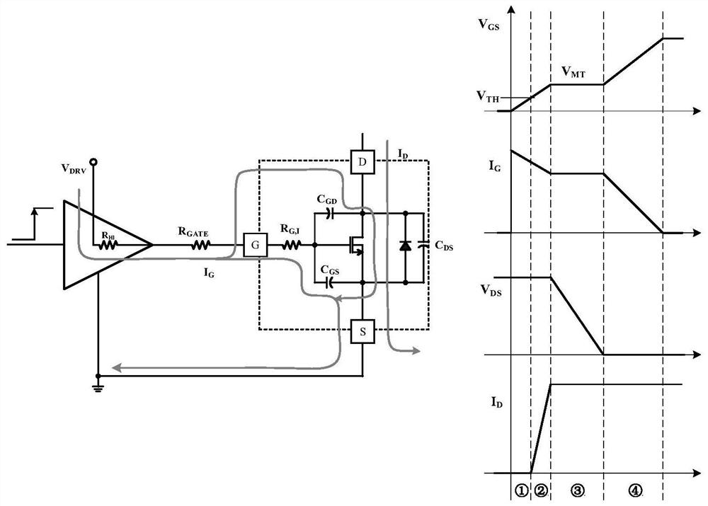
technical field [0001] The invention belongs to the technical field of power supply management, and in particular relates to a grid drive circuit of a power tube with segment drive function, which is used for driving an N-type power tube in a DC-DC converter. Background technique [0002] Power system energy conversion mainly relies on power switches and energy storage elements (inductors and capacitors). Power devices include traditional LDMOS devices and third-generation semiconductor devices, such as silicon-based GaN devices. In DC-DC converters such as Buck topology, the turn-on and turn-off process of power devices is affected by inductance as inductive clamp switching process (Clamp InductiveSwitching). In this mode, the turn-on and turn-off process of power transistors can be achieved through figure 1 The simplified circuit shown is analyzed, in which the role of the inductor is equivalent to a current source. In this mode, the turn-on process of switching power dev...

Claims


Application Information

Patent Timeline
Patent Type & Authority Patents(China)
IPC IPC(8): H02M1/08H02M1/44H02M3/155
CPCH02M1/08H02M1/44H02M3/155
Inventor 明鑫张志文范子威罗淞民王卓张波
Owner UNIV OF ELECTRONICS SCI & TECH OF CHINA
Why Eureka
Eureka Blog
Learn More