A hybrid gate drive circuit

A gate drive circuit and hybrid technology, applied in circuits, electronic switches, electrical components, etc., can solve the problems of long follow-up process, uncontrollable driving speed, and inability to meet the demand for controlling the driving speed of the slope at the same time, and achieve optimization. Electromagnetic interference EMI, enhance anti-crosstalk ability, improve the effect of transient process

Active Publication Date: 2020-11-27
UNIV OF ELECTRONICS SCI & TECH OF CHINA
View PDF5 Cites 0 Cited by
  • Summary
  • Abstract
  • Description
  • Claims
  • Application Information

AI Technical Summary

Problems solved by technology

[0003] Existing gate driving methods usually use triode or field effect transistor alone to drive. As a flow control device, triode can effectively control the charging and discharging speed of the power tube gate. However, due to the existence of built-in potential of triode, it often leads to The follow-up process is too long and not suitable for high-speed application requirements
The driving of field effect transistors (MOSFETs) can avoid this problem, but its driving speed is often uncontrollable
Therefore, the existing gate driving methods cannot meet the requirements for slope control and driving speed at the same time.

Method used


Image

  • A hybrid gate drive circuit
  • A hybrid gate drive circuit
  • A hybrid gate drive circuit

Examples


Embodiment Construction

[0021] Below in conjunction with accompanying drawing and specific embodiment, the present invention will be further elaborated:

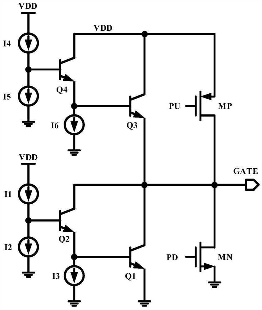
[0022] Such as Figure 4 Shown is an overall block diagram of a hybrid gate drive circuit proposed by the present invention, including a first Darlington tube, a second Darlington tube, a first Darlington tube control module, and a second Darlington tube control module. The module, the first PMOS transistor MP and the first NMOS transistor MN, the first Darlington transistor is connected between the power supply voltage VDD and the output terminal of the hybrid gate drive circuit, and is controlled by the first Darlington transistor control module; The second Darlington tube is connected between the output terminal of the hybrid gate drive circuit and the ground, and is controlled by the second Darlington tube control module; the gate of the first PMOS transistor MP is connected to the first control signal PU, and its source Connect to the power s...


PUM


Abstract

A hybrid gate drive circuit, wherein the first Darlington tube is connected between the power supply voltage and the output terminal of the gate drive circuit, and is controlled by the first Darlington tube control module; the second Darlington tube is connected to the The connection between the output terminal of the gate drive circuit and the ground is controlled by the second Darlington control module; the gate of the first PMOS transistor is connected to the first control signal, the source is connected to the power supply voltage, and the drain is connected to the first NMOS transistor The drain and the output end of the gate drive circuit; the gate of the first NMOS transistor is connected to the second control signal, and the source is grounded. When the power tube is turned on, the second Darlington tube and the first NMOS tube are turned off. First, the first Darlington tube charges the gate of the power tube to the power supply voltage minus the minimum operating voltage of the Darlington tube, and then the first PMOS The tube continues to charge to the power supply voltage; when the power tube is turned off, the first Darlington tube and the first PMOS tube are turned off, and the second Darlington tube discharges the grid of the power tube to the minimum operating voltage of the Darlington tube first. Subsequently, the first NMOS transistor continues to discharge to the ground.

Description

technical field [0001] The invention belongs to the technical field of electronic circuits, and in particular relates to a hybrid gate drive circuit. Background technique [0002] In electronic circuits, the gate drive circuit is an important circuit. The function of the gate drive circuit is to drive the power transistor to turn on and off, and to maintain the on or off state of the power transistor when it is turned on and off in a steady state. The gate drive circuit is widely used in analog circuits. Since the switching speed of the power tube is directly related to the dv / dt experienced by the power during transient switching, in some applications that are sensitive to dv / dt effects (such as AC-DC converters), it is necessary to control the power tube The opening speed to achieve the purpose of reducing the size of dv / dt. [0003] Existing gate driving methods usually use triode or field effect transistor alone to drive. As a flow control device, triode can effectivel...

Claims


Application Information

Patent Timeline
Patent Type & Authority Patents(China)
IPC IPC(8): H02M1/088H02M1/44H03K17/041H03K17/687
CPCH02M1/088H02M1/44H03K17/04106H03K17/687
Inventor 周泽坤刘晓琳钱俊林张波
Owner UNIV OF ELECTRONICS SCI & TECH OF CHINA
Why Eureka
Try Eureka