Optical module system-level batch detection system and method

A batch detection and optical module technology, which is applied in the field of optical communication and network switches, can solve the problem of not being able to cover system-level tests, and achieve the effect of simple operation and high detection efficiency

Inactive Publication Date: 2019-08-20
浪潮思科网络科技有限公司
View PDF7 Cites 5 Cited by
  • Summary
  • Abstract
  • Description
  • Claims
  • Application Information

AI Technical Summary

Problems solved by technology

However, these tests generally can only ensure that the parameters of the module itself are correct, and cannot cover the system-level tests of the module on network devices

Method used

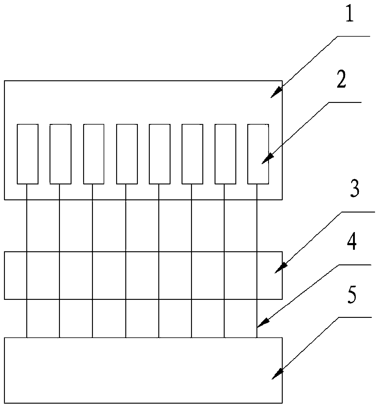
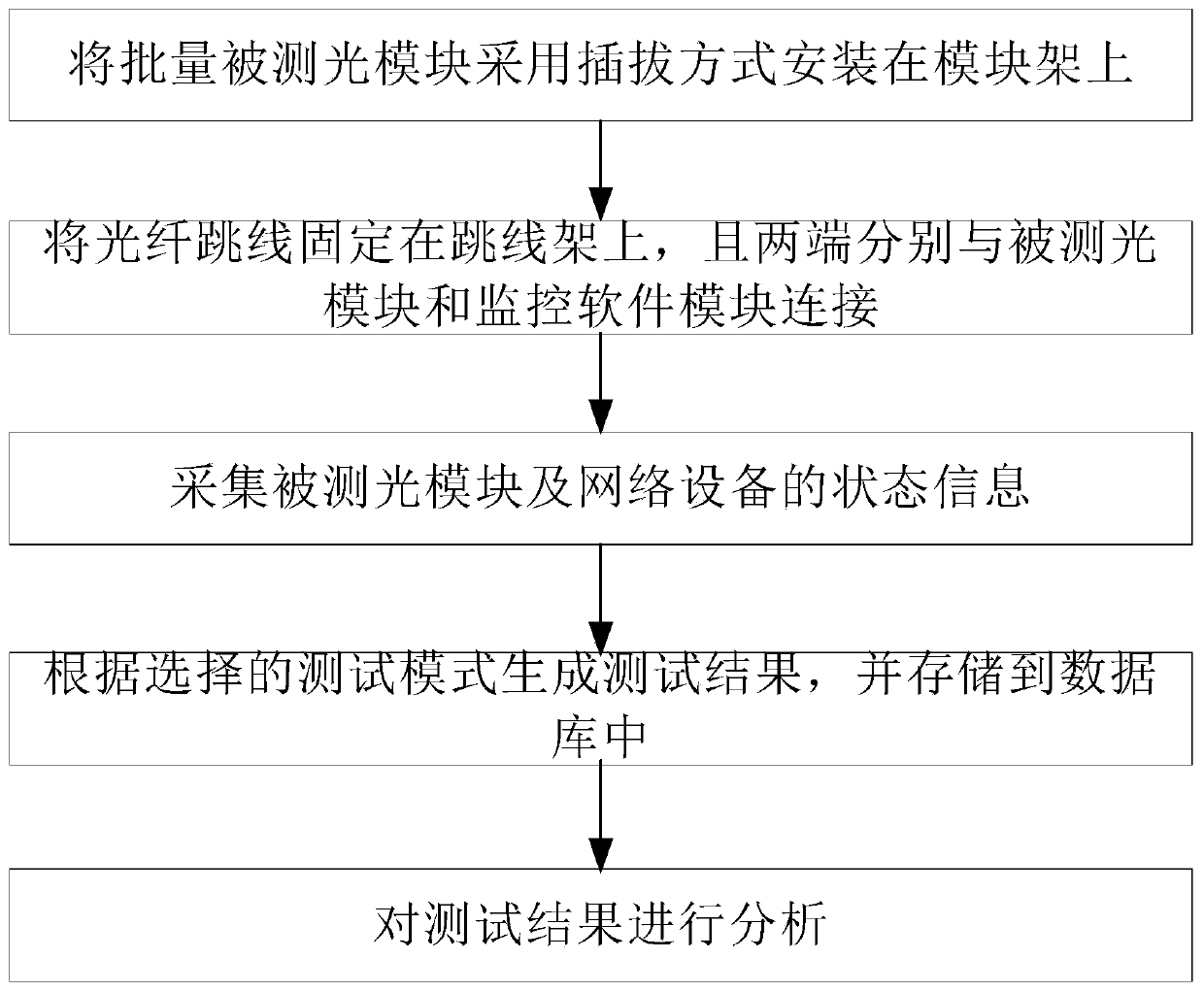
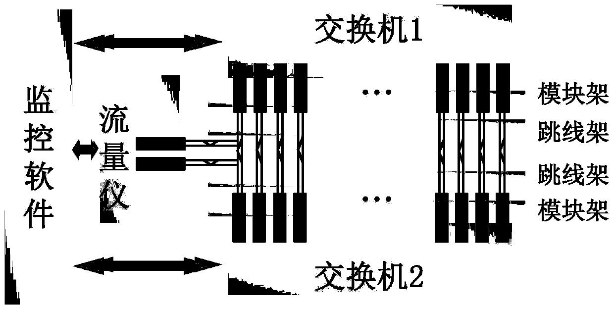

Image

  • Optical module system-level batch detection system and method
  • Optical module system-level batch detection system and method
  • Optical module system-level batch detection system and method

Examples


Embodiment Construction

[0039] Below in conjunction with accompanying drawing and embodiment the present invention will be further described:

[0040] In order to clearly illustrate the technical features of this solution, the present invention will be described in detail below through specific implementation modes and in conjunction with the accompanying drawings. The following disclosure provides many different embodiments or examples for implementing different structures of the present invention. To simplify the disclosure of the present invention, components and arrangements of specific examples are described below. Furthermore, the present invention may repeat reference numerals and / or letters in different instances. This repetition is for the purpose of simplicity and clarity and does not in itself indicate a relationship between the various embodiments and / or arrangements discussed. It should be noted that components illustrated in the figures are not necessarily drawn to scale. Description...


PUM


Abstract

The invention discloses an optical module system-level batch detection system and method, and the system comprises a module frame which is used for fixing optical modules; a jumper frame used for fixing an optical fiber jumper; and a monitoring software module used for acquiring state information of the tested optical module and the network equipment, generating a test result according to the testmode selected by the user, analyzing the test result and storing the test result in a database. The system is used for carrying out system-level batch detection on the optical modules. The operationis simple and the detection efficiency is high. Hot plug testing, power-on and power-off testing, connectivity testing, EEPROM information testing, digital diagnosis testing, flow testing and the likeof the module on network equipment such as a switch and the like can be realized. The system fills the gap of system-level testing between the optical module and network equipment such as a switch, and is widely applied to the aspects of factory delivery detection module quality of optical module manufacturers, switch factory detection hardware welding quality, switch factory detection module compatibility and the like.

Description

technical field [0001] The invention relates to a system and method for system-level batch detection of optical modules, belonging to the technical fields of optical communication and network switches. Background technique [0002] The optical module is composed of optoelectronic devices, functional circuits, and optical interfaces. Its function is photoelectric conversion. The transmitting end converts electrical signals into optical signals. In today's data center applications, optical transceivers play a great role, and in fact they are already the most widely used type of product in data centers. [0003] In the process of producing optical modules, optical module manufacturers generally perform parameter tests on optical modules, such as testing the transmitted optical power, received optical power, and optical eye diagram. However, these tests generally can only ensure that the parameters of the module itself are correct, and cannot cover the system-level tests of the...

Claims


Application Information

Patent Timeline
IPC IPC(8): H04B10/079H04Q11/00
CPCH04B10/079H04Q11/0062H04Q2011/0083
Inventor 李公臣李明刘绍洋
Owner 浪潮思科网络科技有限公司
Why Eureka
Try Eureka