Double frequency conversion optical orthogonal demodulation method and system for microwave signal

A quadrature demodulation, microwave signal technology, applied in electromagnetic wave transmission systems, transmission systems, electrical components, etc., can solve the problems of slow delay adjustment, difficult implementation of optical delay line index technology, large optical insertion loss, etc. The effect of small requests

Active Publication Date: 2019-08-20
CHINA ELECTRONIC TECH GRP CORP NO 38 RES INST
View PDF12 Cites 2 Cited by
  • Summary
  • Abstract
  • Description
  • Claims
  • Application Information

AI Technical Summary

Problems solved by technology

If the local oscillator signal covers a frequency from 0.8GHz to 40GHz, the optical delay line is required to have a delay range of 6.25 to 312.5ps. At the same time, to achieve a phase balance of <±1.8°, the delay line needs to have a step accuracy of 0.125ps.

Method used


Image

  • Double frequency conversion optical orthogonal demodulation method and system for microwave signal
  • Double frequency conversion optical orthogonal demodulation method and system for microwave signal
  • Double frequency conversion optical orthogonal demodulation method and system for microwave signal

Examples


Embodiment 1

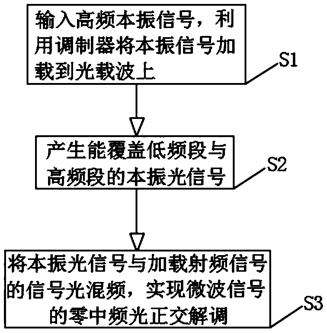
[0044] like figure 1 As shown, this embodiment provides a technical solution: a secondary frequency conversion optical quadrature demodulation method for microwave signals, including the following steps:

[0045] S1: Input the high-frequency local oscillator signal, and use the modulator to load the local oscillator signal onto the optical carrier;

[0046] S2: Generate local oscillator optical signals that can cover low frequency bands and high frequency bands;

[0047] S3: Mix the optical signal of the local oscillator with the optical signal loaded with the radio frequency signal to realize zero-IF optical quadrature demodulation of the microwave signal.

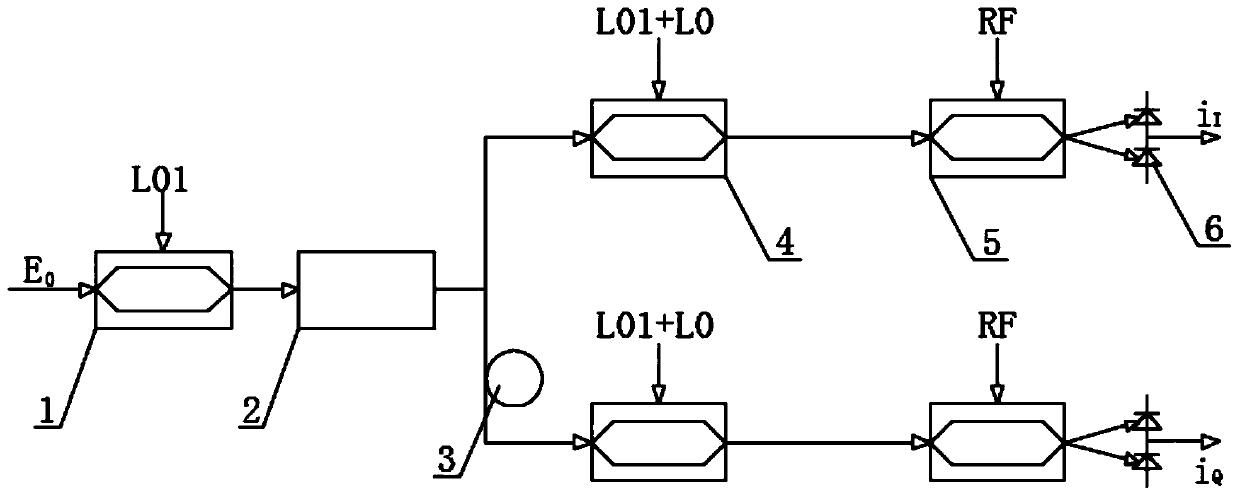
[0048] like figure 2 As shown, further, a double-conversion optical quadrature demodulation method for microwave signals is specifically an optical delay line-based double-conversion optical quadrature modulation and demodulation method.

[0049] In the double-conversion optical quadrature modulation and demodulation ...

Embodiment 2

[0072] like figure 1 As shown, this embodiment provides a technical solution: a secondary frequency conversion optical quadrature demodulation method for microwave signals, including the following steps:

[0073] S1: Input the high-frequency local oscillator signal, and use the modulator to load the local oscillator signal onto the optical carrier;

[0074] S2: Generate local oscillator optical signals that can cover low frequency bands and high frequency bands;

[0075] S3: Mix the optical signal of the local oscillator with the optical signal loaded with the radio frequency signal to realize zero-IF optical quadrature demodulation of the microwave signal.

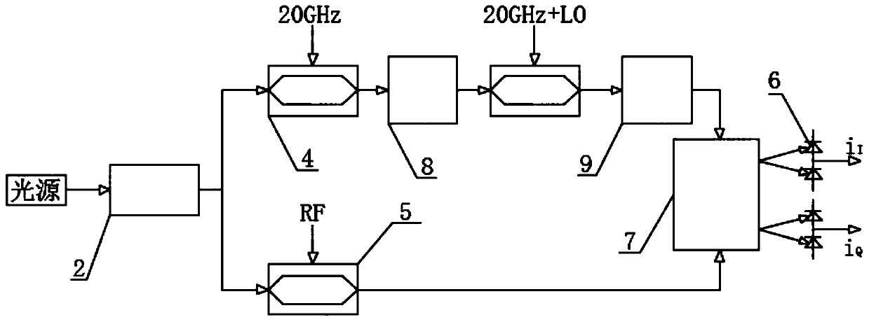
[0076] like image 3 As shown, further, a double-conversion optical quadrature demodulation method for microwave signals is specifically a double-conversion optical quadrature demodulation method based on a 90° optical mixer.

[0077] In the secondary conversion optical quadrature demodulation method based on the 90° o...


PUM


Abstract

The invention discloses a double frequency conversion optical orthogonal demodulation method and system for microwave signals, and belongs to the field of microwave signal processing, and the method comprises the following steps: S1, inputting a high-frequency local oscillator signal, and loading the local oscillator signal to an optical carrier by using a modulator; S2, generating a local oscillator optical signal capable of covering a low frequency band and a high frequency band; and S3, mixing the local oscillation optical signal with the signal light loaded with the radio frequency signalto realize zero intermediate frequency optical orthogonal demodulation of the microwave signal. According to the method, a secondary frequency conversion thought is utilized, and microwave signal processing of a low frequency band is also moved to a high frequency band. The two-stage modulator carries out optical mixing to generate broadband local oscillation optical signals covering a low frequency band and a high frequency band, so that zero intermediate frequency optical orthogonal demodulation of microwave signals is realized, orthogonal demodulation of microwave signals covering a full frequency band can be conveniently realized, and requirements on optical signal processing in a broadband signal optical orthogonal demodulation scheme can be reduced.

Description

technical field [0001] The invention relates to the field of microwave signal processing, in particular to a method and system for secondary frequency conversion optical quadrature demodulation of microwave signals. Background technique [0002] With the development of electronic information technology, the signal frequency band is getting wider and wider. At the same time, in order to simplify the system design, it is hoped to carry out unified intermediate frequency digital signal processing for each frequency band signal. As the front-end equipment for obtaining information, wideband receivers have increasingly strong demands, and the requirements for their technical indicators and environmental adaptability are also getting higher and higher. It can be said that the performance of the receiver plays a very important role in information acquisition. [0003] The traditional method based on pure microwaves to realize ultra-wideband radio frequency signal transmission and ...

Claims


Application Information

Patent Timeline
IPC IPC(8): H04B10/516
CPCH04B10/5165
Inventor 梅理崇毓华朱宇鹏张卫清王冰
Owner CHINA ELECTRONIC TECH GRP CORP NO 38 RES INST
Why Eureka
Try Eureka