Inner and outer wall reinforced soft mechanical arm and manufacturing method thereof

A robotic arm and software technology, applied in the directions of manipulators, claw arms, manufacturing tools, etc., can solve the problems of reducing the efficiency of expansion and bending per unit volume, difficult to adapt to the underwater working environment, complex structure of the software robotic arm, etc., to achieve a simple structure. , cost-effective, light-weight effect

Inactive Publication Date: 2019-08-23
ZHEJIANG UNIV
View PDF7 Cites 2 Cited by
  • Summary
  • Abstract
  • Description
  • Claims
  • Application Information

AI Technical Summary

Problems solved by technology

[0004] At present, there has been some research and application on soft manipulators, but most of the soft manipulators are integrated, and the structure of the soft manipulator is complex, and it is difficult to repair and replace after the cavity is broken. Most of the current soft manipulators are pneumatic, and it is difficult to adapt to the underwater working environment
And the current strengthening of the cavity only stays at the strengthening of the outer wall of the cavity, and the expansion generated during pressurization is in the peripheral direction, which is divided into radial expansion and axial expansion. The axial expansion produces bending, and the radial expansion inhibits bending. , and if the expansion is too large, the cavity will be easily broken, the safety will not be high, and the efficiency of expansion and bending per unit volume will be reduced, which needs to be strictly limited

Method used


Image

  • Inner and outer wall reinforced soft mechanical arm and manufacturing method thereof
  • Inner and outer wall reinforced soft mechanical arm and manufacturing method thereof
  • Inner and outer wall reinforced soft mechanical arm and manufacturing method thereof

Examples


Embodiment Construction

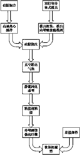
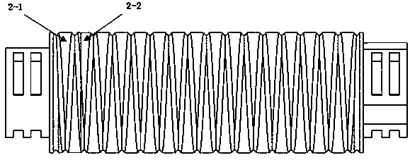
[0054] refer to Figure 1 to Figure 9 , the present invention is made up of several silica gel units through connecting parts, and each silica gel unit has a group of helical grooves 5-3 with the opposite direction of rotation and the same number of turns on the outer wall of the middle part, which are used to wind reinforcing fibers; at both ends of the silica gel unit They are all cylinders with a diameter smaller than the middle part, and there are evenly distributed step-shaped grooves 5-2 on the cylinders, and there are water inlets 5-1; the cavity section of the silica gel unit is three fan-shaped evenly distributed around the axis, And there is a through hole running through the silicone unit.

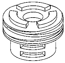
[0055] The connecting part is composed of three petals with the same structure, which are 3D printed with PLA material; the three petal connecting parts form a whole, and the inner surface is composed of evenly distributed step-shaped protrusions 6-1, which are used to connect two...


PUM


Abstract

The invention discloses an inner and outer wall reinforced soft mechanical arm and a manufacturing method thereof. The soft mechanical arm adopts the split type design scheme and comprises a main bodypart and an end cover part. The main body part and the end cover part are manufactured through the split pouring process. The two parts of silica gel are bonded through a special silica gel binding agent. The inner wall of each silica gel unit of the mechanical arm is provided with a through hole penetrating through the silica gel unit. The through holes are used for allowing air pipes of the front end unit to penetrate through. A spring with the appropriate length and rigidity is sealed in the inner wall. The axes of the through holes and the axis of the spring coincide with the axes of thesilica gel units. The spring is placed in a mold in advance and is completely sealed in the inner wall through silica gel pouring. The spring is added to the inner wall of the soft mechanical arm to play a role in supporting the inner wall of the soft mechanical arm, radial expansion of the inner wall of a cavity is greatly limited when the cavity is pressurized to expand, almost no effect on bending of the mechanical arm is caused, the bearable pressure of the cavity is greatly increased, and the expansion bending efficiency of the unit liquid volume is greatly improved.

Description

technical field [0001] The invention relates to a hydraulically driven soft manipulator, in particular to a design and manufacturing method of a soft manipulator module whose inner wall is strengthened by springs and the outer wall is strengthened by fiber winding. Background technique [0002] Traditional rigid robotic arms are generally connected by rigid links through rotating joints. Such rigid robotic arms have the advantages of fast movement, precise trajectory control, and large load-carrying capacity. Due to the rigidity of the structure, they have low degrees of freedom and insufficient flexibility. The adaptability of the environment is poor, and it can only work in a structured environment. [0003] With the continuous advancement of society, there are more new requirements for robotic arms in technology and production. In natural environments and human-centered operations, safety and adaptability to uncertain factors are basic work requirements, while rigid machi...

Claims


Application Information

Patent Timeline
Patent Type & Authority Applications(China)
IPC IPC(8): B25J18/00B29C69/02
CPCB25J18/005B29C69/02
Inventor 王滔祝志鹏孙恩来朱世强
Owner ZHEJIANG UNIV
Why Eureka
Try Eureka