Dust suction system of woodworking engraving machine

A vacuum system and engraving machine technology, applied in wood processing equipment, dust removal, manufacturing tools, etc., can solve the problems of engraving machine vibration, dust suction pipes affecting the quality of dust collection, and unreasonable arrangement of dust suction and chip removal pipes, etc. , to achieve the effects of reducing machine tool vibration, optimizing structure and shortening length

Pending Publication Date: 2019-08-23
JINAN ZHONGKE CNC EQUIP CO LTD
View PDF1 Cites 3 Cited by
  • Summary
  • Abstract
  • Description
  • Claims
  • Application Information

AI Technical Summary

Problems solved by technology

[0003] But the arrangement of the dust-absorbing chip discharge pipeline of the existing woodworking engraving machine is not very reasonable, just fix the dust-absorbing hood on the woodworking engraving machine, the dust-absorbing cover is connected with the vacuum cleaner through the dust-absorbing pipeline, and the length of the dust-absorbing pipeline is too long to affect The quality of dust collection, the corresponding pipe fixing structure will also cause the vibration of the engraving machine

Method used


Image

  • Dust suction system of woodworking engraving machine

Examples


Embodiment Construction

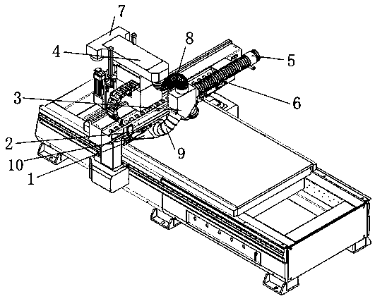
[0014] Such as figure 1 As shown, the dust suction system of the woodworking engraving machine of the present invention includes a top suction head 4 , a dust suction joint 3 , a dust suction pusher cover 1 and a dust suction pipe 6 . The dust suction joint 3 has four interfaces, the two interfaces on the bottom surface are connected to the vacuum pusher cover 1, the upper interface is connected to the top suction head 4, and the right side interface is connected to the dust outlet pipe 6 to discharge wood chips and dust.

[0015] The top suction head 4 is installed on the top of the woodworking engraving machine. The top suction head 4 has two front and rear ports. upper interface. Spindle suction cover 7 sucks dust and sawdust in processing and sends into top suction head 4, enters dust suction joint 3 by top suction head 4 again. The vacuum pusher cover 1 is connected to the beam of the woodworking engraving machine through two telescopic cylinders 2. The telescopic cylin...


PUM


Abstract

The invention provides dust suction system of a woodworking engraving machine. The system involves a main shaft dust suction cover, a top suction head, a dust suction connector, a dust suction and material pushing cover and a dust suction pipeline; one end hole of the top suction head is connected with the main shaft dust suction cover, and the other end hole of the top suction head is connected with the dust suction connector; and the outlet of the dust suction and material pushing cover is connected with the dust suction connector, and the dust suction connector is connected with the dust suction pipeline. The top suction head is firstly arranged at the top of the woodworking engraving machine, the dust suction connector and the dust suction and material pushing cover are arranged on a cross beam of the woodworking engraving machine, dust and saw dust are sucked into the main shaft dust suction cover to be sent to the top suction head, then enters from the top suction head to the dust suction connector, the dust suction and material push cover moves along with the cross beam of the woodworking engraving machine, and wood can be pushed to advance while the dust is sucked. The dustsuction pipeline is connected with a dust collector to discharge the dust and the saw dust. According to the system, the functions of all parts are fully utilized, and the structure optimization of the dust suction system of the woodworking engraving machine is realized. In the working process, the saw dust and the dust enter from the main shaft dust suction cover and the dust suction and material pushing cover, are conveyed out by the dust suction pipeline, a dust suction hole is increased, and the length of the dust suction pipeline is shortened.

Description

technical field [0001] The invention relates to a dust collection system for woodworking engraving machines, belonging to the technical field of woodworking engraving machines dust collection. Background technique [0002] With the development of the woodworking and woodcarving industry, the application of woodworking engraving machines has become more and more extensive, and single manual operations have gradually turned to automated operations. An important problem that has always plagued the majority of woodworking engraving machine manufacturers and users is that a lot of dust and a lot of wood chips will be generated during the engraving machine processing process, which will inevitably affect the processing quality and working environment. Therefore, most woodworking engraving machines are equipped with dust suction and chip removal devices. [0003] But, the arrangement of the dust-absorbing chip discharge pipe of existing woodworking engraving machine is not very re...

Claims


Application Information

Patent Timeline
Patent Type & Authority Applications(China)
IPC IPC(8): B27G3/00B08B15/04
CPCB08B15/04B27G3/00
Inventor 候丙科
Owner JINAN ZHONGKE CNC EQUIP CO LTD
Why Eureka
Try Eureka