
A laser coaxial wire feeding metal parts forming device with variable wire feeding angle

A technology for coaxial wire feeding and metal parts, applied in tin feeding devices, metal processing equipment, metal material coating technology, etc., can solve problems such as many optical problems, insufficient coupling of optical materials, complex optical paths, etc., and achieve laser energy High utilization rate, improved laser utilization rate, high material utilization effect

Active Publication Date: 2021-02-23
KUNMING UNIV OF SCI & TECH
View PDF7 Cites 0 Cited by
  • Summary
  • Abstract
  • Description
  • Claims
  • Application Information

AI Technical Summary

Problems solved by technology

Although this method solves the problem of the anisotropy of the melt channel shape caused by the different directions of laser cladding in the optical lateral wire feeding technology, and ensures the consistency of all directions, but due to the difference between the wire feeding nozzle and the laser beam Coaxiality cannot be guaranteed, which may easily lead to problems such as insufficient optical material coupling
[0006] However, the internal optical wire feeding cladding technology has a complex internal optical path, many optical problems, and is difficult to completely control. At the same time, the complexity of the optical path also causes the laser to be reflected and absorbed by the inner wall of the nozzle for many times, and its laser utilization rate is low.

Method used


Image

  • A laser coaxial wire feeding metal parts forming device with variable wire feeding angle
  • A laser coaxial wire feeding metal parts forming device with variable wire feeding angle
  • A laser coaxial wire feeding metal parts forming device with variable wire feeding angle

Examples


Embodiment 1

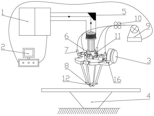
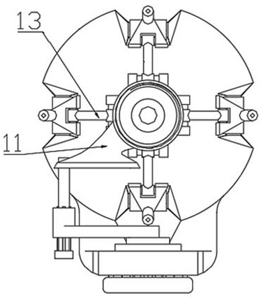
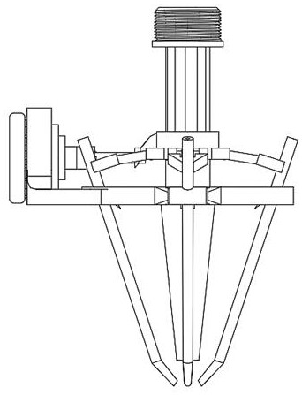
[0037] Embodiment 1: as Figure 1~4 , 6, a laser coaxial wire feeding metal parts forming device with a variable wire feeding angle, including a focusing mirror 5, a laser generator 1, a wire feeding system 9, a shielding gas system 8, and an optical wire control system 2. The wire system 9 includes a wire feeder, a wire feed pipeline 7 and a variable wire feed angle nozzle 12. The wire feeder communicates with the variable wire feed angle nozzle 12 through the wire feed pipeline 7. The laser generator 1 and the wire feed system 9 are respectively connected to the The light filament control system 2 is electrically connected, the laser transmission channel and the laser output channel are all set on the machine tool or multi-axis robot, the focusing mirror 5 is set at the junction of the laser transmission channel and the laser output channel, and the end of the laser output channel is connected to the laser nozzle. The top is fixedly connected, the laser from the laser genera...

Embodiment 2

[0045] Embodiment 2: as Figure 1~6 As shown, a laser coaxial wire feeding metal parts forming device with variable wire feeding angle includes a focusing mirror 5, a laser generator 1, a wire feeding system 9, a shielding gas system 8, an optical wire control system 2, and a wire feeding system 9 includes a wire feeder, a wire feed pipe 7 and a variable wire feed angle nozzle 12. The wire feeder communicates with the variable wire feed angle nozzle 12 through the wire feed pipe 7. The laser generator 1 and the wire feed system 9 are respectively connected to the light wire The control system 2 is electrically connected, the laser transmission channel and the laser output channel are both set on the machine tool or multi-axis robot, the focusing mirror 5 is set at the junction of the laser transmission channel and the laser output channel, and the end of the laser output channel is fixed to the top of the laser nozzle connection, the laser from the laser generator 1 is injecte...

Embodiment 3

[0055] Embodiment 3: as Figure 1~6 As shown, a laser coaxial wire feeding metal parts forming device with variable wire feeding angle includes a focusing mirror 5, a laser generator 1, a wire feeding system 9, a shielding gas system 8, an optical wire control system 2, and a wire feeding system 9 includes a wire feeder, a wire feed pipe 7 and a variable wire feed angle nozzle 12. The wire feeder communicates with the variable wire feed angle nozzle 12 through the wire feed pipe 7. The laser generator 1 and the wire feed system 9 are respectively connected to the light wire The control system 2 is electrically connected, the laser transmission channel and the laser output channel are both set on the machine tool or multi-axis robot, the focusing mirror 5 is set at the junction of the laser transmission channel and the laser output channel, and the end of the laser output channel is fixed to the top of the laser nozzle connection, the laser from the laser generator 1 is injecte...


PUM


Abstract

The invention relates to a laser coaxial wire feeding metal part forming device with a variable wire feeding angle, which belongs to the technical field of laser near-net shaping. The device includes a focusing mirror, a laser generator, a wire feeding system, a shielding gas system, and a light wire control system. The wire feeding system includes a wire feeding machine, a wire feeding pipeline and a nozzle with a variable wire feeding angle. The variable wire feeding angle nozzle is connected, the laser generator and the wire feeding system are electrically connected to the optical fiber control system respectively, the outer wall of the middle part of the laser nozzle is fixed with a wire feeding pipeline bearing plate, and the top of the laser nozzle is vertically provided with a slide rail, the slide rail The upper slide is equipped with a ring slider, the side end of the ring slider is hinged with a connecting rod, the other end of the connecting rod is hinged with the top of the wire feeding pipe, and the middle part of the wire feeding pipe is set on the wire feeding pipe bearing plate through a rotating connector. At the side end, the shielding gas system is fixed on the outside of the variable wire feeding angle nozzle at the end of the wire feeding pipeline.

Description

technical field [0001] The invention relates to a laser coaxial wire feeding metal part forming device with a variable wire feeding angle, which belongs to the technical field of laser near-net shaping. Background technique [0002] In laser cladding, the laser and metal cladding materials are supplied to the processing position synchronously, and the metal cladding materials are continuously and uniformly fed into the focused laser spot, and the key point is to ensure the precise coupling of the light powder. [0003] The traditional laser powder feeding cladding process is relatively mature, but there are inevitable problems of powder divergence and lag. In order to ensure the continuity of cladding, only part of the metal powder sprayed at high speed participates in the forming, resulting in low utilization of powder materials , and the dust in the working process has brought great harm to the environment; in addition, this technology has higher requirements on the partic...

Claims


Application Information

Patent Timeline
Patent Type & Authority Patents(China)
IPC IPC(8): C23C24/10B23K1/005B23K3/06
CPCB23K1/0056B23K3/063C23C24/103
Inventor 张晓伟王明宗蒋业华刘洪喜
Owner KUNMING UNIV OF SCI & TECH
Learn More