Combined control mechanism

A combined control and combined valve technology, applied in mechanical equipment, engine components, valve operation/release devices, etc., can solve the problems of complex structure, high cost, large volume, etc., and achieve small size, low cost, and simple control logic. Effect

Pending Publication Date: 2019-08-23
A O SMITH CHINA WATER HEATER CO LTD +1
View PDF0 Cites 0 Cited by
  • Summary
  • Abstract
  • Description
  • Claims
  • Application Information

AI Technical Summary

Problems solved by technology

[0003] Therefore, the structure of the wastewater in the prior art is more complicated than that of the solenoid valve, the cost is higher, the required parts are more, and the volume is larger

Method used


Image

  • Combined control mechanism
  • Combined control mechanism
  • Combined control mechanism

Examples


Embodiment Construction

[0030] The details of the present application can be understood more clearly with reference to the accompanying drawings and the description of specific embodiments of the present application. However, the specific implementation manners of the application described here are only for explaining the purpose of the application, and cannot be construed as limiting the application in any way. Under the teaching of the present application, skilled persons can conceive any possible modifications based on the present application, and these should be regarded as belonging to the scope of the present application.

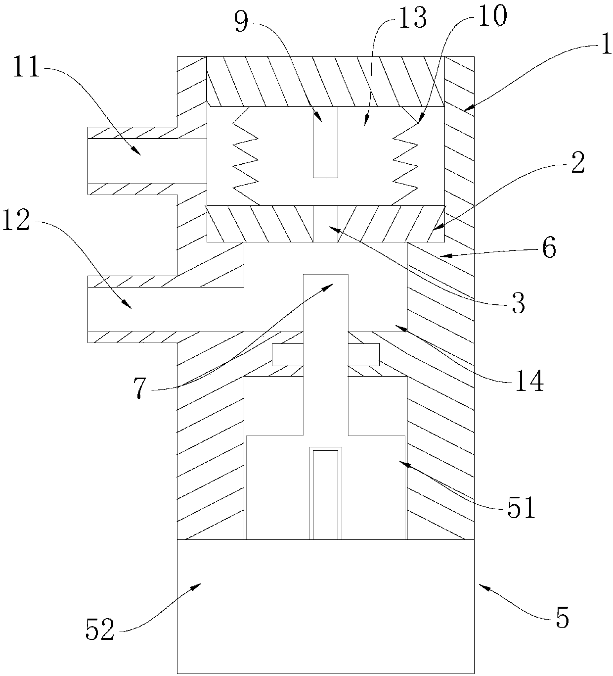
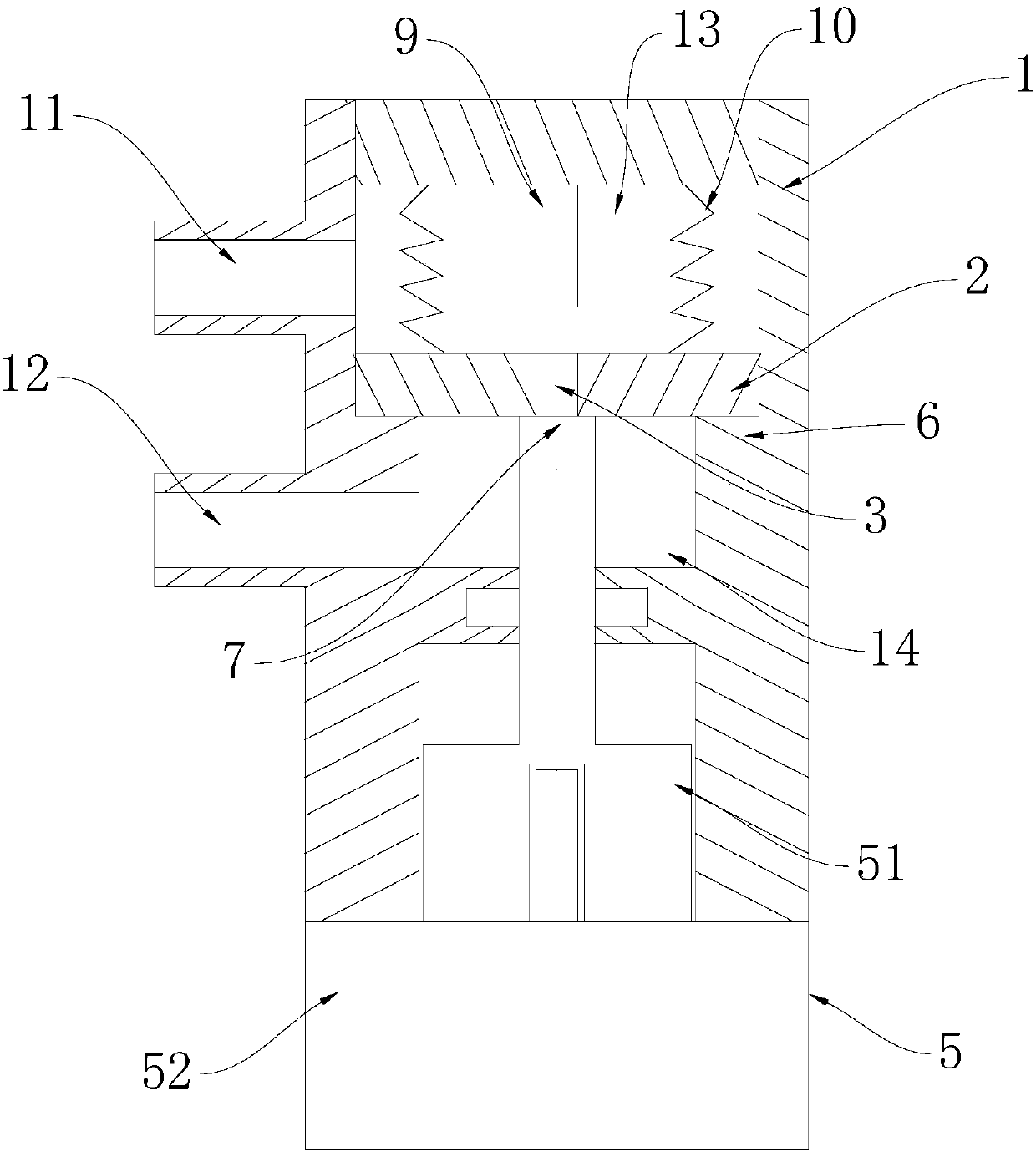
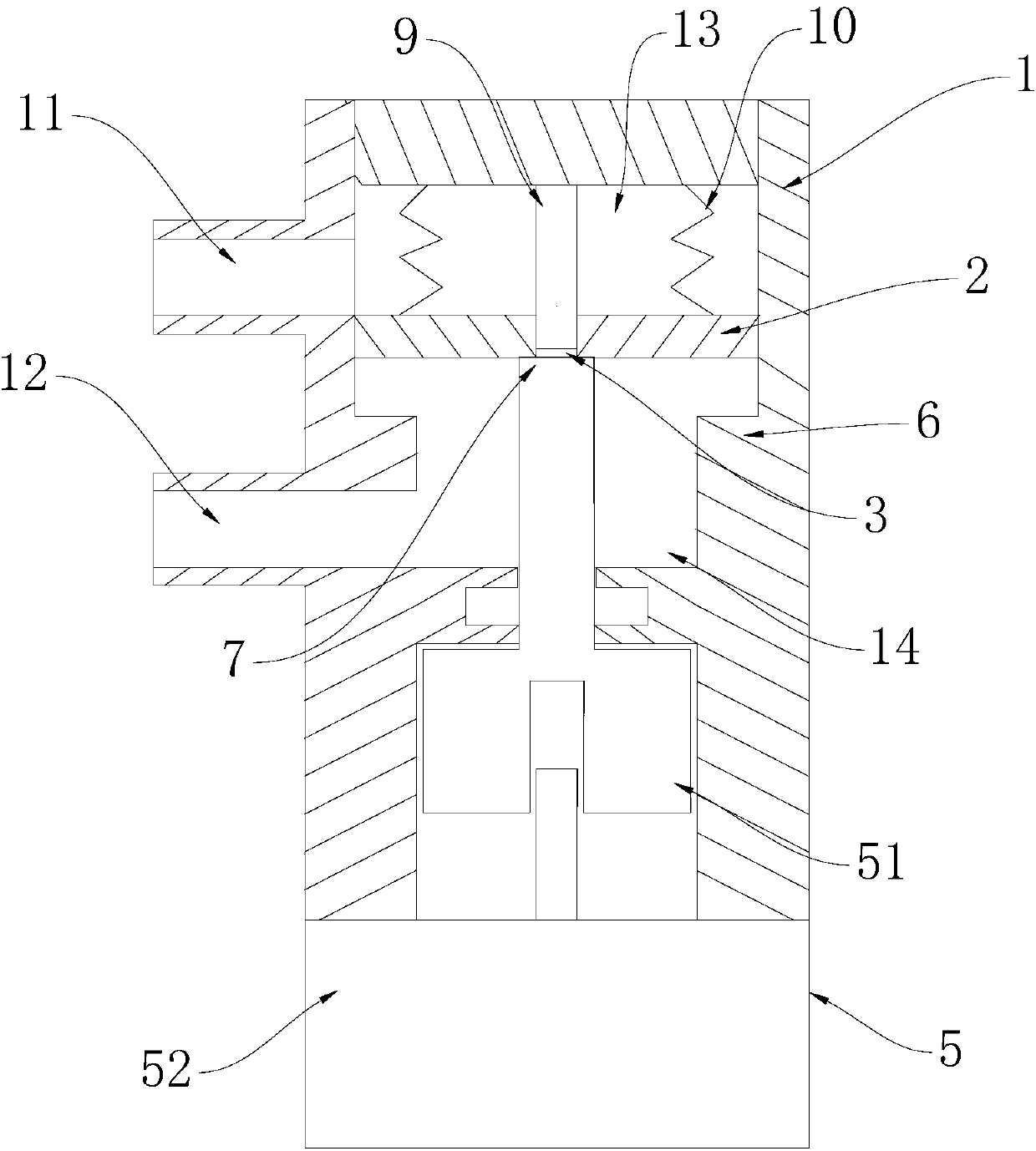
[0031] The embodiment of the present application discloses a combined control mechanism, which includes a housing 1 . The casing 1 is provided with a water inlet 11 and a water outlet 12 . The housing 1 is provided with a controlled component 2 and a control component 5 capable of controlling the controlled component 2 . The controlled part 2 divides the housing 1 into a f...


PUM


Abstract

The embodiment of the invention discloses a combined control mechanism. The combined control mechanism comprises a shell, a controlled component, a control component, a first passage and a second passage, wherein the shell is provided with a water inlet and a water outlet; the controlled component is arranged in the shell and divides the shell into a first cavity and a second cavity, the first cavity communicates with the water inlet, and the second cavity communicates with the water outlet; the control component can control the controlled component to move relative to the shell; the first cavity can communicate with the second cavity through the first passage; the first cavity can also communicate with the second cavity through the second passage; or, the first cavity can communicate withthe second cavity only through the first passage or only through the second passage. The combined control mechanism has the advantages that the structure is simple, the number of parts is small, thecost is low, and the size is small. According to the combined control mechanism, a throttling state, a flushing state and a closing state can be achieved through one control component, and only the position of the control component needs to be controlled, so that the control logic is simple.

Description

technical field [0001] The present application relates to the field of fluid control, in particular to a combined control mechanism. Background technique [0002] In the prior art, generally a waste water ratio electromagnetic valve is set at the waste water outlet of the filter membrane (such as reverse osmosis membrane or nanofiltration membrane, etc.) of the water purifier. Usually, the waste water ratio electromagnetic valve includes a first flow channel arranged in parallel and a second flow channel provided with a flushing electromagnetic valve. When the filter membrane of the water purifier is in the filtering state, the flushing solenoid valve is closed, and the filtered waste water flows out of the waste water ratio solenoid valve from the first channel under the action of the water pressure at the water inlet end. When the filter membrane of the water purifier is in the flushing state, the flushing electromagnetic valve is opened, and most of the water after rinsi...

Claims


Application Information

Patent Timeline
Patent Type & Authority Applications(China)
IPC IPC(8): F16K1/32F16K1/36F16K1/54F16K31/04F16K47/02B01D61/10B01D61/02
CPCB01D61/025B01D61/027B01D61/10F16K1/32F16K1/36F16K1/54F16K31/046F16K47/02
Inventor 徐大明程兆山陈晓艳
Owner A O SMITH CHINA WATER HEATER CO LTD
Why Eureka
Try Eureka