Manufacturing method for high pressure tank

A manufacturing method and high-pressure tank technology, applied in the field of high-pressure tank manufacturing, can solve problems such as low fatigue strength, and achieve the effect of suppressing the reduction of fatigue strength

Inactive Publication Date: 2019-08-23
TOYOTA JIDOSHA KK
View PDF8 Cites 1 Cited by
  • Summary
  • Abstract
  • Description
  • Claims
  • Application Information

AI Technical Summary

Problems solved by technology

As a result, even if a compressive stress is applied to the lining by autotightening, the fatigue strength of each boundary portion may be lower than that of the lining due to the influence of the tensile stress acting on the boundary portion during the autotightening treatment. The fatigue strength of other parts is low

Method used


Image

  • Manufacturing method for high pressure tank
  • Manufacturing method for high pressure tank
  • Manufacturing method for high pressure tank

Examples


Embodiment Construction

[0032] Hereinafter, a method of manufacturing a high-pressure tank according to an embodiment of the present invention and other embodiments will be described with reference to the drawings.

[0033] [implementation mode]

[0034] 1. About the high pressure tank 1

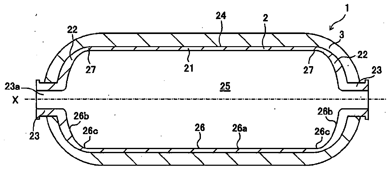
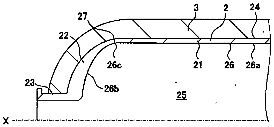
[0035] First, refer to figure 1 as well as figure 2 The high-pressure tank 1 according to this embodiment will be described. figure 1 It is a schematic sectional view of the high-pressure tank 1 which concerns on this embodiment. figure 2 yes figure 1 A schematic enlarged cross-sectional view in the vicinity of the boundary portion 27 of the high-pressure tank 1 is shown. also, figure 1 as well as figure 2 is a cross-sectional view along the axis X of the high-pressure tank 1 .

[0036] The high-pressure tank 1 according to this embodiment is used in natural gas vehicles, fuel cell vehicles, and the like. Such as figure 1 As shown, the high-pressure tank 1 includes a liner 2 and a reinforcement layer 3...


PUM


Abstract

A manufacturing method for a high pressure tank includes preparing a liner including a cylindrical body portion and a pair of side end portions, forming a reinforcing layer by winding fiber-reinforcedresin around an outer peripheral surface of the liner, carrying out shot peening by shooting a shot material towards an inner periphery region of a boundary between the body portion and each of the side end portions, and carrying out autofrettage after the reinforcing layer is formed and the shot peening is carried out. The autofrettage is carried out by applying internal pressure to the liner such that the liner is plastically deformed and then eliminating the internal pressure such that compression stress is applied to the liner.

Description

technical field [0001] The present invention relates to a method of manufacturing a high-pressure tank including a metal liner that accommodates gas, and a reinforcement layer made of fiber-reinforced resin formed on the outer peripheral surface of the liner. Background technique [0002] Conventionally, gas such as hydrogen gas supplied to a fuel cell is stored in a high-pressure tank in a pressurized state. Such a high-pressure tank includes a metal liner that accommodates gas, and a reinforcement layer made of fiber-reinforced resin formed on the outer peripheral surface of the liner. For example, Japanese Patent Application Laid-Open No. 2016-89891 discloses a technique in which, in such a method of manufacturing a high-pressure tank, a self-tightening process of applying internal pressure to the lining to plastically deform the lining is disclosed. [0003] However, the boundary portion (shoulder portion) between the main body of the liner and the dome-shaped side ends...

Claims


Application Information

Patent Timeline
Patent Type & Authority Applications(China)
IPC IPC(8): F17C1/06
CPCF17C1/06F17C2201/0109F17C2201/035F17C2201/056F17C2203/0619F17C2203/0643F17C2203/0646F17C2203/0648F17C2203/066F17C2203/067F17C2209/2154F17C2209/2181F17C2209/224F17C2209/23F17C2209/232F17C2209/234F17C2221/012F17C2223/035F17C2260/011F17C2270/0165B24C1/10F17C2203/0604F17C2203/0639F17C2203/0663F17C2203/068F17C2203/0695F17C2221/033F17C2223/0123F17C2223/036F17C2270/0168Y02E60/32F17C1/02F17C2203/012Y10T29/49801Y10T29/49805
Inventor 仲田好宏
Owner TOYOTA JIDOSHA KK
Why Eureka
Try Eureka