
Fabric-based capacitive sensor and manufacturing method thereof

A technology of a capacitive sensor and a manufacturing method, which is applied in the direction of converting the output of the sensor and transmitting the sensing components and instruments by means of an electromagnetic/magnetic device, can solve the problems of complex manufacturing process, high cost, poor flexibility, etc., and achieves low cost, Real-time monitoring and low-cost effects

Active Publication Date: 2019-08-23
XI'AN POLYTECHNIC UNIVERSITY
View PDF6 Cites 6 Cited by
  • Summary
  • Abstract
  • Description
  • Claims
  • Application Information

AI Technical Summary

Problems solved by technology

[0004] The purpose of the present invention is to provide a fabric-based capacitive sensor, which solves the problems of poor flexibility and high cost of existing capacitive sensors
[0005] Another object of the present invention is to provide the manufacturing method of the above-mentioned fabric-based capacitive sensor, which solves the problem of complex manufacturing process of the existing capacitive sensor

Method used


Image

  • Fabric-based capacitive sensor and manufacturing method thereof
  • Fabric-based capacitive sensor and manufacturing method thereof
  • Fabric-based capacitive sensor and manufacturing method thereof

Examples


Embodiment 1

[0054] Step 1. Select the plain weave fabric, cut it into a size of 70mm×70mm, soak the plain weave fabric in alcohol with a volume fraction of 75% for 10 minutes, and ultrasonic power is 80W; take out the plain weave fabric after ultrasonic cleaning with deionized water, and then statically air dry;

[0055] Step 2. Immerse the dried plain weave fabric in the graphene dispersion, then ultrasonic the above plain weave fabric for 20min, the ultrasonic power is 40W, leave it to air dry, and iron the air dried plain weave fabric with an iron;

[0056] Wherein, the dispersion is composed of graphene, polyvinylpyrrolidone and deionized water mixed with a mass ratio of 0.01:0.2:100, wherein the solid content of graphene in the dispersion is 0.01wt%;

[0057] Step 3. Paste conductive copper foil on the upper and lower surfaces of the ironed plain fabric. The length of the conductive copper foil is 40mm, the width is 3mm, and the thickness is 30μm. The conductive copper foil is far aw...

Embodiment 2

[0063] The manufacturing method of this capacitive sensor based on fabric is the same as embodiment 1, the difference is:

[0064] The fabric dielectric layer 2 is a twill fabric;

[0065] In step 1, the time of ultrasonic treatment is 15min, and the power is 80W;

[0066] In step 2, the time of ultrasonic treatment is 25min, and the power is 50W;

[0067] The dispersion is composed of carbon nanotubes, polyvinylpyrrolidone and deionized water mixed with a mass ratio of 0.03:0.7:100, and the solid content of carbon nanotubes in the dispersion is 0.03wt%;

[0068] The length of the conductive copper foil is 45mm and the width is 4mm;

[0069] In step 5, the mass ratio of polydimethylsiloxane and Dow Corning 184 silicone rubber is 5:1;

[0070] In step 6, the curing time is 90 minutes, and the temperature is 70°C.

Embodiment 3

[0072] The manufacturing method of this capacitive sensor based on fabric is the same as embodiment 1, the difference is:

[0073] The fabric dielectric layer 2 is a satin weave fabric;

[0074] In step 1, the time of ultrasonic treatment is 20min, and the power is 70W;

[0075] In step 2, the time of ultrasonic treatment is 30min, and the power is 60W;

[0076] The dispersion liquid is composed of conductive carbon black, polyvinylpyrrolidone and deionized water in a mass ratio of 0.05:1.25:100, and the solid content of the conductive carbon black in the dispersion liquid is 0.05wt%;

[0077] The length of the conductive copper foil is 50mm and the width is 5mm;

[0078] In step 5, the mass ratio of polydimethylsiloxane and Dow Corning 184 silicone rubber is 8:1;

[0079] In step 6, the curing time is 105 minutes, and the temperature is 65°C.


PUM


Abstract

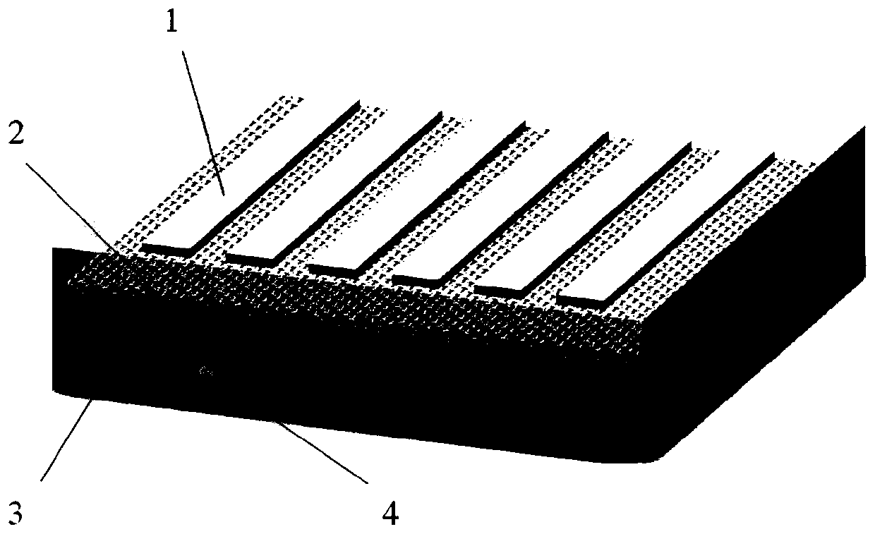
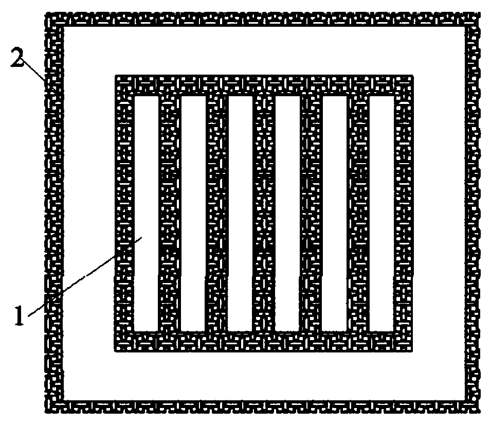
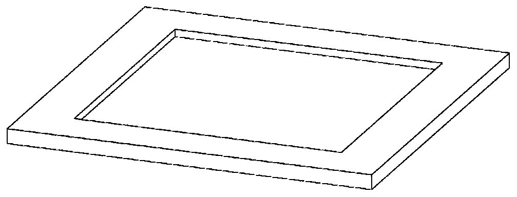
The invention discloses a fabric-based capacitive sensor. The fabric-based capacitive sensor comprises an electrode layer a and an electrode layer b, wherein a fabric dielectric layer is arranged between the electrode layer a and the electrode layer b, the electrode layer a, the electrode layer b and the fabric dielectric layer are all solidified and encapsulated through an encapsulating material,and the electrode layer a and the electrode layer b are both connected with leads. The invention also discloses a manufacturing method of the fabric-based capacitive sensor, which comprises the following steps: firstly, pretreating the fabric dielectric layer, then soaking the fabric dielectric layer in the dispersion liquid, and taking out after ultrasonic treatment; printing a mould through a 3D printer, adhering a conductive copper foil to the surface of the fabric dielectric layer, placing the fabric dielectric layer into the mould, and clamping the mould; and pouring the prepared encapsulating material into the mould, standing, and then placing the molud into a curing furnace for curing treatment to finally obtain the fabric-based capacitive sensor. The fabric-based capacitive sensorsolves the problems of poor flexibility and high manufacturing cost of the existing capacitive sensor.

Description

technical field [0001] The invention belongs to the technical field of flexible wearable electronic devices, relates to a fabric-based capacitive sensor, and also relates to a manufacturing method of the capacitive sensor. Background technique [0002] Smart textiles are a kind of textiles that highly integrate electronic technology and fabrics. In addition to maintaining the basic functions of traditional textiles, they also have functions such as monitoring, information processing and communication. It has broad application prospects. Smart textiles are generally composed of sensors, actuators, data processing, communication, and power supplies. Sensors are the key for smart textiles to realize the interaction between the human body and the outside world, which requires the sensors to have good flexibility, high sensitivity and fast response. Traditional sensors are mostly composed of metals and semiconductors, and have poor coupling with fabrics. After direct integration...

Claims


Application Information

Patent Timeline
Patent Type & Authority Applications(China)
IPC IPC(8): G01D5/241
CPCG01D5/2417
Inventor 肖渊张威李红英
Owner XI'AN POLYTECHNIC UNIVERSITY
Learn More