Electric energy recycling device
A technology of electric energy recovery and current, which is applied in the direction of circuit devices, harmonic reduction devices, electrical components, etc., can solve the problems of secondary utilization and the current that returns to the neutral line cannot be recycled, so as to reduce waste and improve utilization rate Effect
- Summary
- Abstract
- Description
- Claims
- Application Information
AI Technical Summary
Problems solved by technology
Method used
Image
Examples
Embodiment 1
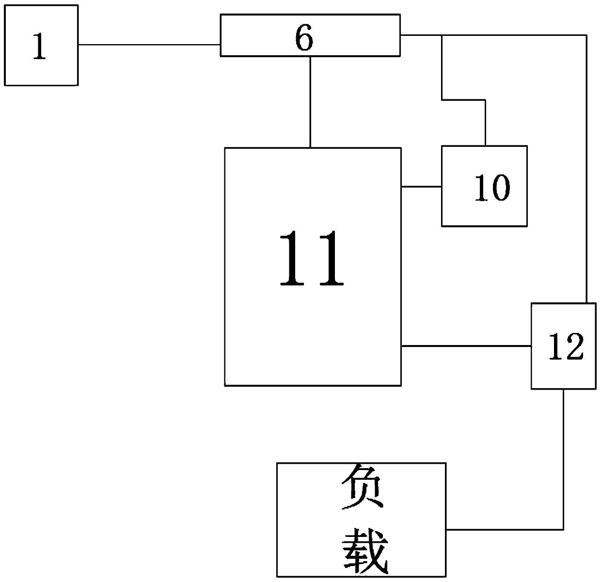
[0026] For a device for recovering and reusing electric energy provided by Embodiment 1 of the present invention, refer to figure 2 As shown, it includes: dual-term controller 11, which is used to control the output direction of the current; reactor 6, which is used to limit the voltage drop on the grid side when the converter commutates, suppress harmonics and decoupling of parallel converter groups , to limit the jump of the grid voltage or the current impact generated during the operation of the grid system; the current sampler 10 is used to collect the state information of the current in the AC circuit, and transmit the collected information to the dual-term controller 11; the intermediate relay 9 , control the power on and off of the circuit; after the current enters the reactor 6 through the neutral line N, after the reactor is initially stabilized, the information of the stable state of the current is transmitted to the dual-phase controller, and the dual-phase controll...
Embodiment 2
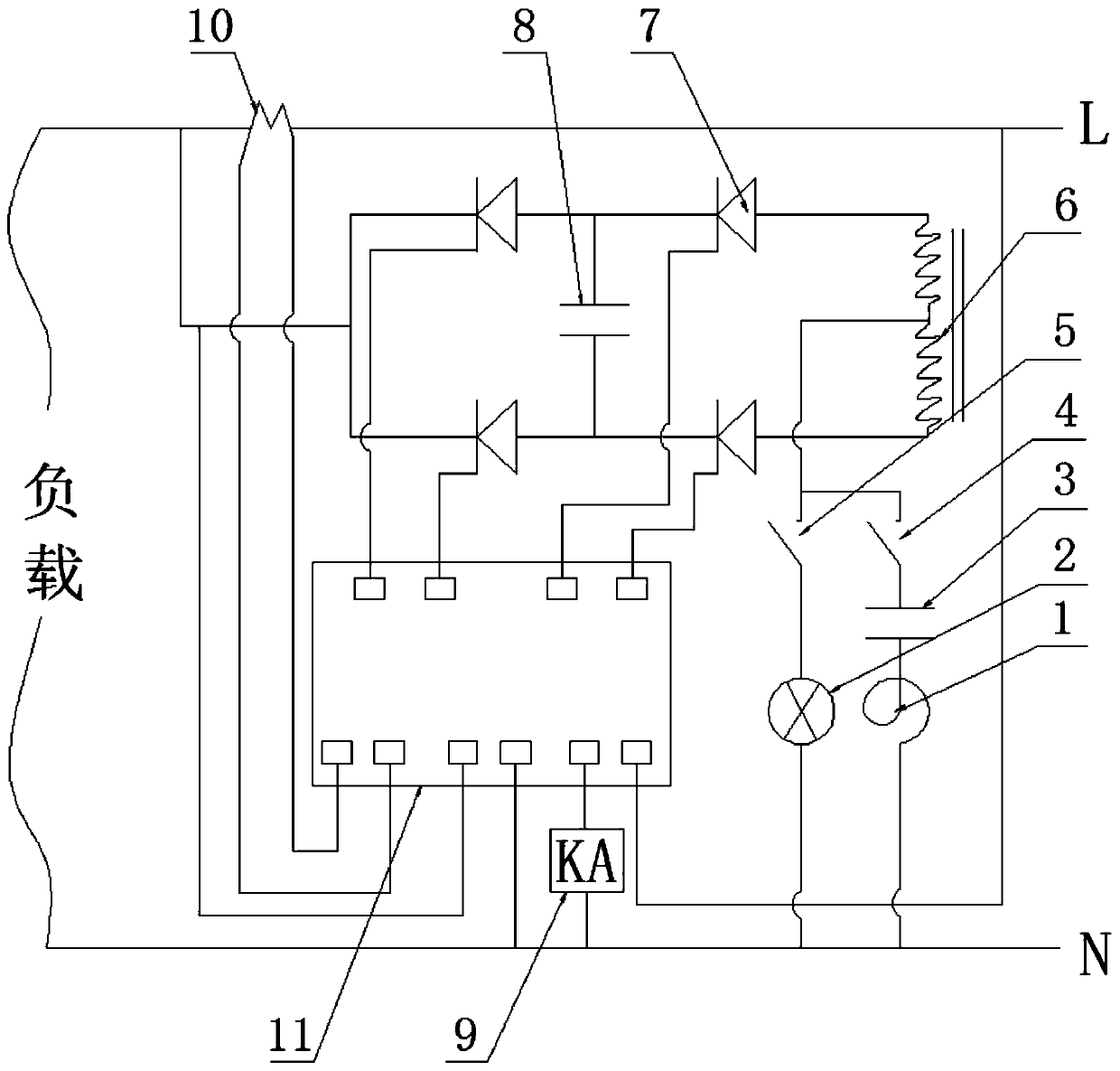
[0029] An electric energy recovery and reuse device provided in Embodiment 2 of the present invention, please continue to refer to figure 1As shown, the dual-term controller 11 is used to control the output direction of the current; the reactor 6 is used to limit the voltage drop on the grid side during the commutation of the converter, suppress harmonics and decoupling of the parallel converter group, limit The grid voltage jump or the current impact generated by the grid system operation; the current sampler 10 is used to collect the state information of the current in the AC circuit, and transmit the collected information to the dual-term controller 11; the intermediate relay 9 controls The power on and off of the circuit; after the current enters the reactor 6 through the neutral line N, after the initial stabilization of the reactor, the information of the steady state of the current is transmitted to the dual-phase controller, and the dual-phase controller receives the st...
Embodiment 3
[0033] An electric energy recovery and reuse device provided in Embodiment 3 of the present invention is preferably, figure 1 As shown, when in use, connect the current output terminal of the device to the power input terminal of the electrical appliance, for example, connect one of the contacts of the lamp to the live line L, and the other contact to the neutral line N. After the intermediate relay is energized, the line is connected. The light bulb is on, and the dual-phase controller 11 is used to control the output direction of the current; the reactor 6 is used to limit the voltage drop on the grid side when the converter commutates, suppress harmonics and solve the problem of the parallel converter group Coupling, to limit the jump of the grid voltage or the current impact generated during the operation of the grid system; the current sampler 10 is used to collect the state information of the current in the AC circuit, and transmit the collected information to the dual-te...
PUM
 Abstract
Description
Claims
Application Information
 - R&D
- Intellectual Property
- Life Sciences
- Materials
- Tech Scout
- Unparalleled Data Quality
- Higher Quality Content
- 60% Fewer Hallucinations
Browse by: Latest US Patents, China's latest patents, Technical Efficacy Thesaurus, Application Domain, Technology Topic, Popular Technical Reports.
© 2025 PatSnap. All rights reserved.Legal|Privacy policy|Modern Slavery Act Transparency Statement|Sitemap|About US| Contact US: help@patsnap.com


