High-integration flywheel energy storage device with novel horizontal self-vacuum chamber

A high-integration, flywheel energy storage technology, applied in the field of flywheel energy storage, can solve the problems of low integration, complex control, low energy storage density, etc., to broaden the application range, improve integration, increase pumping rate and The effect of the compression ratio

Active Publication Date: 2019-08-23
JIANGSU UNIV
View PDF5 Cites 5 Cited by
  • Summary
  • Abstract
  • Description
  • Claims
  • Application Information

AI Technical Summary

Problems solved by technology

[0006] The purpose of the present invention is to overcome the shortcomings of traditional flywheel energy storage devices such as low integration, complicated control and low energy storage density, and propose a flywheel energy storage device with a three-degree-of-freedom magnetic bearing and a single-winding outer rotor bearingless motor. The structure and control method of the flywheel energy storage device are simplified, while the integration and energy storage density of the flywheel energy storage system are improved, and the cost and loss are reduced

Method used


Image

  • High-integration flywheel energy storage device with novel horizontal self-vacuum chamber
  • High-integration flywheel energy storage device with novel horizontal self-vacuum chamber
  • High-integration flywheel energy storage device with novel horizontal self-vacuum chamber

Examples


Embodiment Construction

[0035] In order to make the object, technical solution and advantages of the present invention more clear, the present invention will be further described in detail below in conjunction with examples. It should be understood that the specific implementation described here is only suitable for explaining the present invention, and is not intended to limit the present invention.

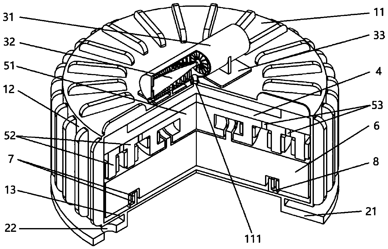
[0036] Such as figure 1 As shown, the exterior of the energy storage device of the present invention is a cavity formed by the casing 1. The casing is composed of an upper end cover 11, a casing body 12 and a lower end cover 13. The upper end of the casing body 12 is tightly and fixedly connected with the upper end cover 11. The casing body 12 The lower end is tightly and fixedly connected with the lower end cover 13 . A central hole 111 is opened in the center of the upper end cover 11, through which the molecular pump sucks the air in the cavity to form a vacuum environment in the cavity. The shell...


PUM


Abstract

The invention discloses a high-integration flywheel energy storage device with a novel horizontal self-vacuum chamber. A vacuum chamber is formed through a casing, an upper end of the vacuum chamber is a three-degree-of-freedom magnetic bearing fixedly connected with the casing by a bracket, which includes a radial magnetic bearing, an axial magnetic bearing and a permanent magnet, a lower end ofthe three-degree-of-freedom magnetic bearing is a flywheel rotor, a single-winding outer rotor bearingless motor is located at a lower end of the flywheel rotor, a rotor of the motor is mounted in anannular groove at a lower surface of the flywheel rotor, and a stator is fixed to a lower end of the casing by a bracket. The device is advantaged in that five-degree-of-freedom balance of the flywheel rotor is realized by the three-degree-of-freedom magnetic bearing combined with the single-winding outer rotor bearingless motor, a control mode is simplified, the integration degree is improved, ahorizontal composite vacuum pump is arranged at an upper end of the casing, a vacuum pump is a double-rotor structure which is mirror-symmetrical to the left and right, and the vacuum degree and the pumping speed are improved.

Description

technical field [0001] The invention relates to the technical field of flywheel energy storage, and specifically refers to a flywheel energy storage device in which a three-degree-of-freedom magnetic bearing cooperates with a single-winding outer rotor bearingless motor to achieve five-degree-of-freedom balance, and adopts a horizontal vacuum pump to self-evacuate. Background technique [0002] With the rapid development of the global economy, the consumption of natural resources is increasing day by day. Human beings are facing the major problems of depletion of natural resources and environmental pollution. Utilize existing energy efficiently and actively develop advanced energy storage technologies. The traditional chemical storage battery has high energy storage density and low price, and is widely used, but it needs regular maintenance, short life, large energy loss, long charging time, and brings pollution to the environment. Because the flywheel energy storage system...

Claims


Application Information

Patent Timeline
Patent Type & Authority Applications(China)
IPC IPC(8): H02K7/02H02K7/09
CPCH02K7/025H02K7/09Y02E60/16
Inventor 张维煜杨启富程烨东朱熀秋
Owner JIANGSU UNIV
Why Eureka
Try Eureka