Three-level Boost circuit and multi-output parallel system

A three-level, output series technology, applied in high-efficiency power electronic conversion, output power conversion device, DC power input conversion to DC power output, etc., can solve problems such as not being able to meet voltage withstand requirements

Pending Publication Date: 2019-08-23
SUNGROW POWER SUPPLY CO LTD
View PDF0 Cites 11 Cited by
  • Summary
  • Abstract
  • Description
  • Claims
  • Application Information

AI Technical Summary

Problems solved by technology

[0002] With the rise of power electronic converter system voltage, the withstand voltage requirements for related switching devices are also gradually increasing. However, due to the influence of semiconductor process performance and other aspects, the development of cost-effective devices has a certain lag, and it cannot meet the relevant requirements in the short term. Therefore, how to use lower voltage level devices to achieve high-voltage power changes at a lower cost has become a research hotspot, and the proposal of multi-level technology can better solve this problem

Method used


Image

  • Three-level Boost circuit and multi-output parallel system
  • Three-level Boost circuit and multi-output parallel system
  • Three-level Boost circuit and multi-output parallel system

Examples


Embodiment Construction

[0054] The following will clearly and completely describe the technical solutions in the embodiments of the present invention with reference to the accompanying drawings in the embodiments of the present invention. Obviously, the described embodiments are only some, not all, embodiments of the present invention. Based on the embodiments of the present invention, all other embodiments obtained by persons of ordinary skill in the art without making creative efforts belong to the protection scope of the present invention.

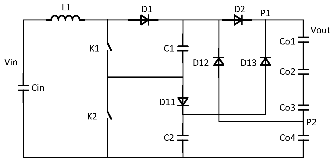
[0055] see figure 1 , the embodiment of the present invention discloses a three-level Boost circuit, including an input capacitor Cin, an inductor L1, a first switch K1, a second switch K2, a first freewheeling diode D1, a second freewheeling diode D2, and a flying capacitor C1, balancing capacitor C2, charging diode D11, clamping diode D12, discharging diode D13 and output series capacitor group Co (label "Co" is not in figure 1 shown in ), where:

[0056] ...


PUM


Abstract

The invention discloses a three-level Boost circuit and a multi-output parallel system, which prevent overvoltage damage of a switching device. The circuit comprises capacitors Cin and C1-C2, an inductor L1, switches K1-K2, diodes D1-D2 and D11-D13, and an output series capacitor group Co. Nodes P1 and P2 are arranged in the output series capacitor group Co; the negative electrode of the capacitorCin is connected with a low-potential end of the output series capacitor group Co; the positive electrode of the capacitor Cin is connected with a high-potential end of the output series capacitor group Co through the first end of the L1, the second end of the L1, the anode of D1, the cathode of D1, the anode of D2 and the cathode of D2 in sequence; the second end of the L1 is connected with a negative electrode of the Cin through the first end of the K1, the second end of the K1, the first end of the K2 and the second end of the K2 in sequence; the cathode of the D1 is connected with the negative electrode of the Cin through the anode of the C1, the anode of D11, the anode of D11 and the C2 in sequence; the second end of K1 is connected with the anode of D11; the anode of D12 is connected with the anode of D2, and the anode of D12 is connected with P2; the cathode of the D13 is connected with the P1, and the anode of the D13 is connected with the cathode of the D11; and K1 and K2 arealternately conducted.

Description

technical field [0001] The invention relates to the technical field of power electronics, more specifically, to a three-level Boost circuit and a multi-channel output parallel system. Background technique [0002] With the rise of power electronic converter system voltage, the withstand voltage requirements for related switching devices are also gradually increasing. However, due to the influence of semiconductor process performance and other aspects, the development of cost-effective devices has a certain lag, and it cannot meet the relevant requirements in the short term. Therefore, how to use lower voltage level devices to realize high-voltage power changes at a lower cost has become a research hotspot, and the proposal of multi-level technology can better solve this problem. [0003] The power change includes step-up conversion, step-down conversion, buck-boost conversion, etc. The present invention only focuses on preventing overvoltage damage to switching devices durin...

Claims


Application Information

Patent Timeline
Patent Type & Authority Applications(China)
IPC IPC(8): H02M3/07H02M1/32
CPCH02M3/07H02M1/32H02M3/158H02M3/1584H02M1/36H02M1/0095H02M3/1552H02M1/322
Inventor 王腾飞庄加才徐君潘年安
Owner SUNGROW POWER SUPPLY CO LTD
Why Eureka
Try Eureka