Laser scanning unit and laser printer

A technology of laser scanning and laser beams, which is applied in the direction of optical components, optics, instruments, etc., can solve the problems of high mold precision requirements, high manufacturing costs, and complex optical design, so as to optimize component layout design, save costs, and ensure optical quality. The effect of the characteristic

Inactive Publication Date: 2019-08-27
至像科技有限公司
View PDF8 Cites 3 Cited by
  • Summary
  • Abstract
  • Description
  • Claims
  • Application Information

AI Technical Summary

Problems solved by technology

[0005] Therefore, the technical problem to be solved by the present invention is to overcome the complex optical design of the FTL lens in the prior art, resulting in a long development cycle; extremely high mold precision requirements, high manufacturing costs and other defects, thereby providing a laser scanning unit and a laser printer

Method used


Image

  • Laser scanning unit and laser printer
  • Laser scanning unit and laser printer

Examples


Embodiment Construction

[0021] The technical solutions of the present invention will be clearly and completely described below in conjunction with the accompanying drawings. Apparently, the described embodiments are some of the embodiments of the present invention, but not all of them. Based on the embodiments of the present invention, all other embodiments obtained by persons of ordinary skill in the art without making creative efforts belong to the protection scope of the present invention.

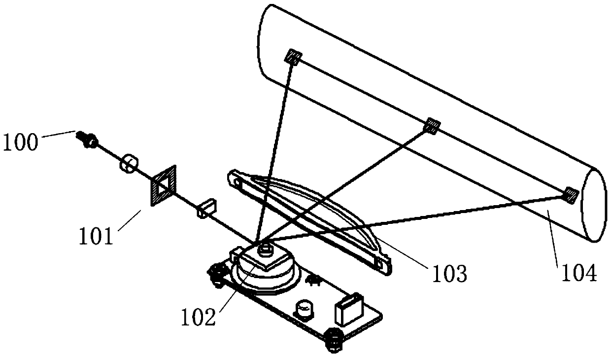
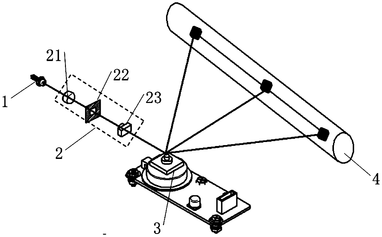
[0022] figure 2 An embodiment of a laser scanning unit provided by the present invention is shown. The laser scanning unit includes a laser generator (LD) 1 , a collimator lens group 2 , a polygon mirror motor 3 and a light receiving surface (OPC) 4 arranged along the optical path.

[0023] Wherein, the laser generator 1 is used to generate and emit a laser beam. The laser beam emitted by the laser generator 1 is scattered light, and its scattering angles in the vertical direction and the horizontal directi...


PUM


Abstract

The invention provides a laser scanning unit and a laser printer. The laser scanning unit comprises a laser diode, a collimating lens group, a polygonal mirror motor and an organic photo conductor which are set along a light path. The collimating lens group comprises shaping lenses which enable divergence angles of laser beams emitted by the laser diode to be equal in a vertical direction and a parallel direction. According to the design, only single-time optical shaping and focusing are required and the focusing does not need to be carried out for the beam rotationally reflected by the polygonal mirror motor, at each angle, so a design verification period for optical development is greatly reduced. Compared with the prior art, the laser scanning unit and the laser printer have the advantages that an FTL lens is avoided, so development cost is reduced and production cost is greatly reduced. Control over accumulated tolerance is facilitated through reduction of optical elements, and optical performance is relatively stable.

Description

technical field [0001] The invention relates to the technical field of laser scanning devices, in particular to a laser scanning unit and a laser printer. Background technique [0002] In current laser printers, the laser unit mostly adopts a laser scanning unit (LSU) and a laser matrix (LPH). Such as figure 1 As shown, the laser scanning unit on the market includes a laser generator (LD) 100 , a collimator lens group 101 , a polygon mirror motor 102 , an FTL lens 103 and an optical receiving surface (OPC) 104 . The laser beam emitted by the laser generator is a divergent beam. The divergent beam passes through the collimator lens group and focuses on the mirror surface of the polygon mirror motor once; the laser light reflected by the polygon mirror motor diverges, passes through the FTL lens, and is focused on the surface of the light-receiving surface for the second time. Focus to form a spot. The photosensitive coating on the surface of the light-receiving surface rec...

Claims


Application Information

Patent Timeline
Patent Type & Authority Applications(China)
IPC IPC(8): G02B26/12G02B27/09G02B17/02G03G15/04
CPCG02B17/023G02B26/124G02B27/0916G02B27/0955G03G15/0409
Inventor 唐波炯蒋维
Owner 至像科技有限公司
Why Eureka
Try Eureka