Self-bypass type fault current limiter and control method thereof
A fault current limiter and control method technology, applied in circuit devices, emergency protection circuit devices, emergency protection circuit devices for limiting overcurrent/overvoltage, etc. The problems of large loss and large floor space of the DC current limiter can achieve the effect of flexible transfer, saving investment and small loss resistance.
- Summary
- Abstract
- Description
- Claims
- Application Information
AI Technical Summary
Problems solved by technology
Method used
Image
Examples
Embodiment 1
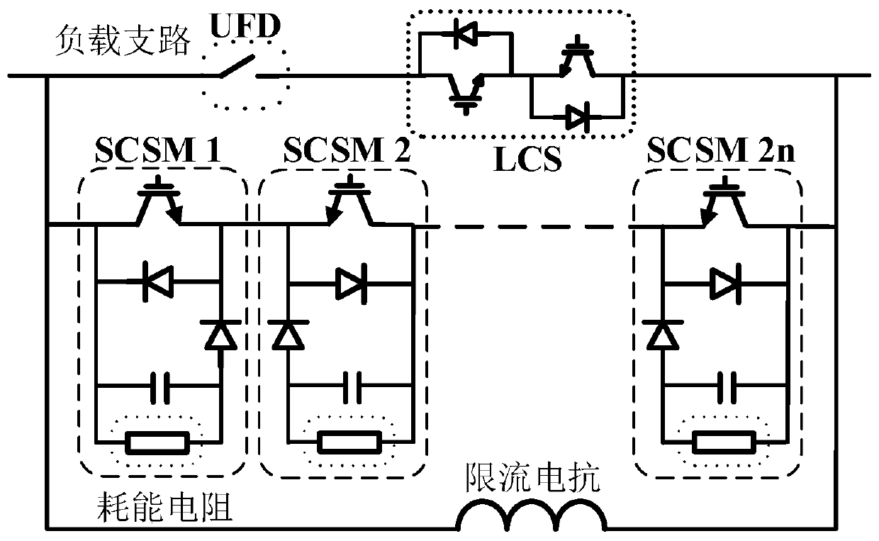
[0044] Embodiment 1 of the present invention provides a self-bypass type fault current limiter, which specifically includes a current flow branch, a current transfer branch and a current limiting branch. The functions of each branch are as follows:
[0045] The current-through branch is used to realize the conduction of the steady-state current of the DC line when the DC line is in normal operation, and transfer the fault current to the current-limiting branch after detecting a fault in the DC line;
[0046] Among them, the current transfer branch is used to carry the fault current transferred by the flow-through branch, and force the current-limiting element in the current-limiting branch to connect to the DC line;
[0047] Among them, the current-limiting branch is used to increase the system damping and reduce the rising speed of the fault current after being connected in series with the DC line.
[0048]The flow-through branch above includes a fast isolating switch K1 and ...
Embodiment 2
[0054] Embodiment 2 of the present invention provides a control method of a self-bypass type fault current limiter, and the specific process is as follows:
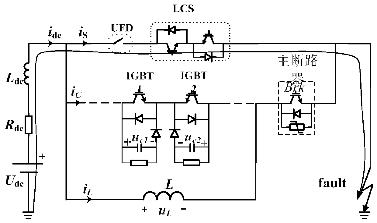
[0055] The DC line where the self-bypass type fault current limiter is located is in normal operation and before the fault is detected, the IGBT1 and IGBT2 in the current-passing branch are turned on, the IGBTs in the current transfer branch are all blocked, the current-limiting branch is out of operation, and the current-limiting branch is out of operation. IGBT1 and IGBT2 in the flow branch are turned on, the steady state current or fault current flows through the flow branch, the DC line operates normally and before a fault occurs on the DC line where the self-bypass fault current limiter is detected, the steady state The current or fault current flows through the flow-through branch, and the schematic diagram of the flow path of the DC line fault current before the fault is detected is shown in figure 2 shown.
Embodiment 3
[0057] The control method of the self-bypass type fault current limiter provided by Embodiment 3 of the present invention is suitable for detecting a fault on the DC line where the self-bypass type fault current limiter is located, and the specific process is as follows:
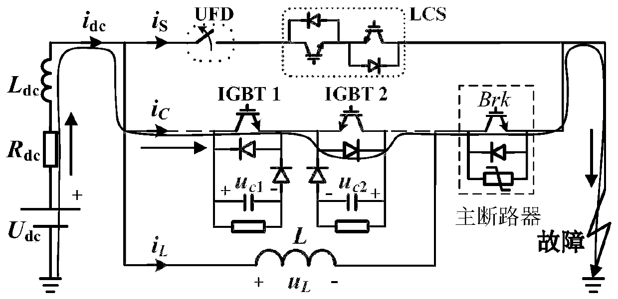
[0058] S101: All IGBTs in the current-passing branch are turned off, all sub-modules in the current transfer branch are turned on, and all capacitors in the single-clamp sub-module are in a bypass state. The schematic diagram of the fault current flow path is as follows image 3 shown;
[0059] S102: Block all sub-module IGBTs in the main branch circuit. At this time, the capacitors in the main branch circuit are connected in series to facilitate fast charging. The current-limiting reactor and the capacitor are connected in parallel at this time, and the increase of the capacitor voltage will cause the fault current to transfer to the reactor. The schematic diagram of the flow path of the fault current is a...
PUM
 Abstract
Description
Claims
Application Information
 - R&D
- Intellectual Property
- Life Sciences
- Materials
- Tech Scout
- Unparalleled Data Quality
- Higher Quality Content
- 60% Fewer Hallucinations
Browse by: Latest US Patents, China's latest patents, Technical Efficacy Thesaurus, Application Domain, Technology Topic, Popular Technical Reports.
© 2025 PatSnap. All rights reserved.Legal|Privacy policy|Modern Slavery Act Transparency Statement|Sitemap|About US| Contact US: help@patsnap.com


