Gearbox assembling production facility

A technology for production equipment and gearboxes, which is applied in the field of gearbox assembly production equipment, which can solve problems such as uneven adhesion, large workshop space, and uneven extrusion deformation of gaskets, so as to avoid repeated positioning errors, improve assembly accuracy, Good for mass production

Inactive Publication Date: 2019-08-30
重庆市綦江区自力汽配有限公司
View PDF5 Cites 2 Cited by
  • Summary
  • Abstract
  • Description
  • Claims
  • Application Information

AI Technical Summary

Problems solved by technology

[0003] However, the existing artificial assembly is difficult to overcome the following technical deficiencies:
[0004] First, when manual dispensing is used, it is necessary to dispens glue one by one in the gasket ring groove of the cover joint of the gearbox, which has the problems of large position deviation, poor alignment, long operation time and heavy workload;
[0005] Second, when the gasket is manually inserted into the gasket ring groove of the gearbox with glue, there will be uneven force in all directions when the gasket is installed, and any unevenness will occur when the gasket is snapped into the gasket ring groove Flat, and at the same time, it cannot be evenly bonded with the glue in the gasket ring groove, and at the same time, the gasket squeezes the glue in the gasket ring groove in an orderly manner, resulting in uneven distribution of glue, uneven bonding, and uneven deformation of the gasket by extrusion , the problem of inconsistent circumferential seal;
[0006] Third, different operations are required to be completed on different equipment, requiring multiple transfers and clamping, occupying a large workshop space, and there are problems such as low automation, low processing efficiency, and high production costs.

Method used


Image

  • Gearbox assembling production facility
  • Gearbox assembling production facility
  • Gearbox assembling production facility

Examples


Embodiment Construction

[0046] Below in conjunction with accompanying drawing and embodiment the present invention will be further described:

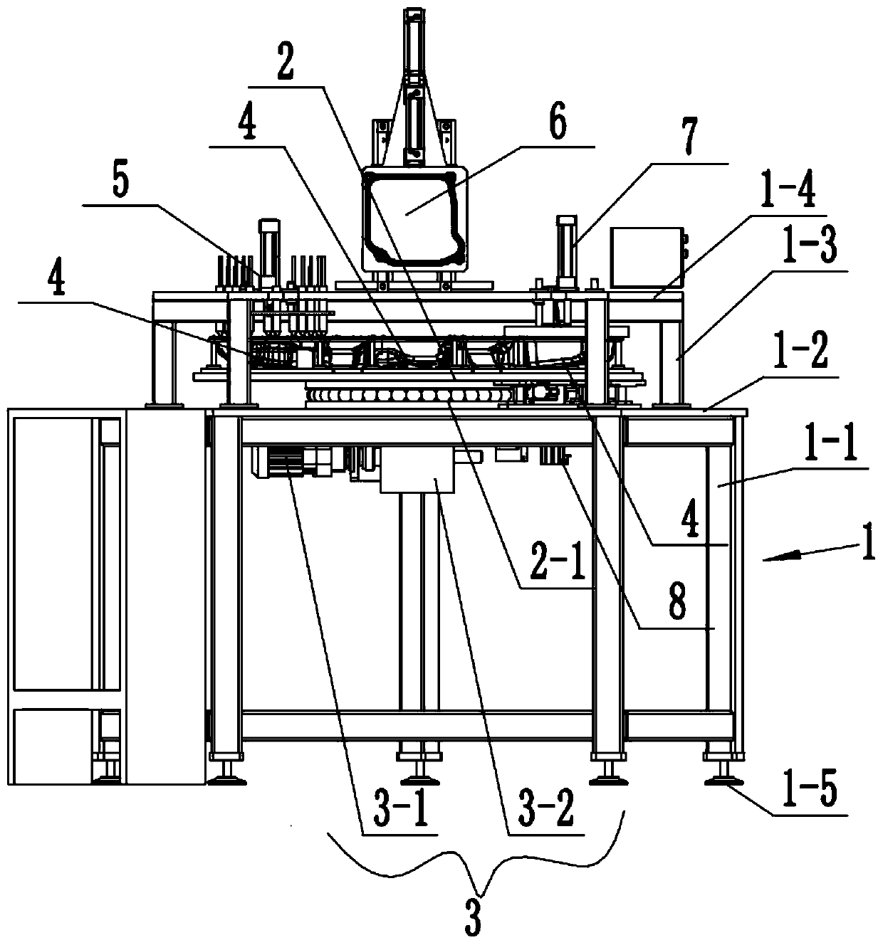
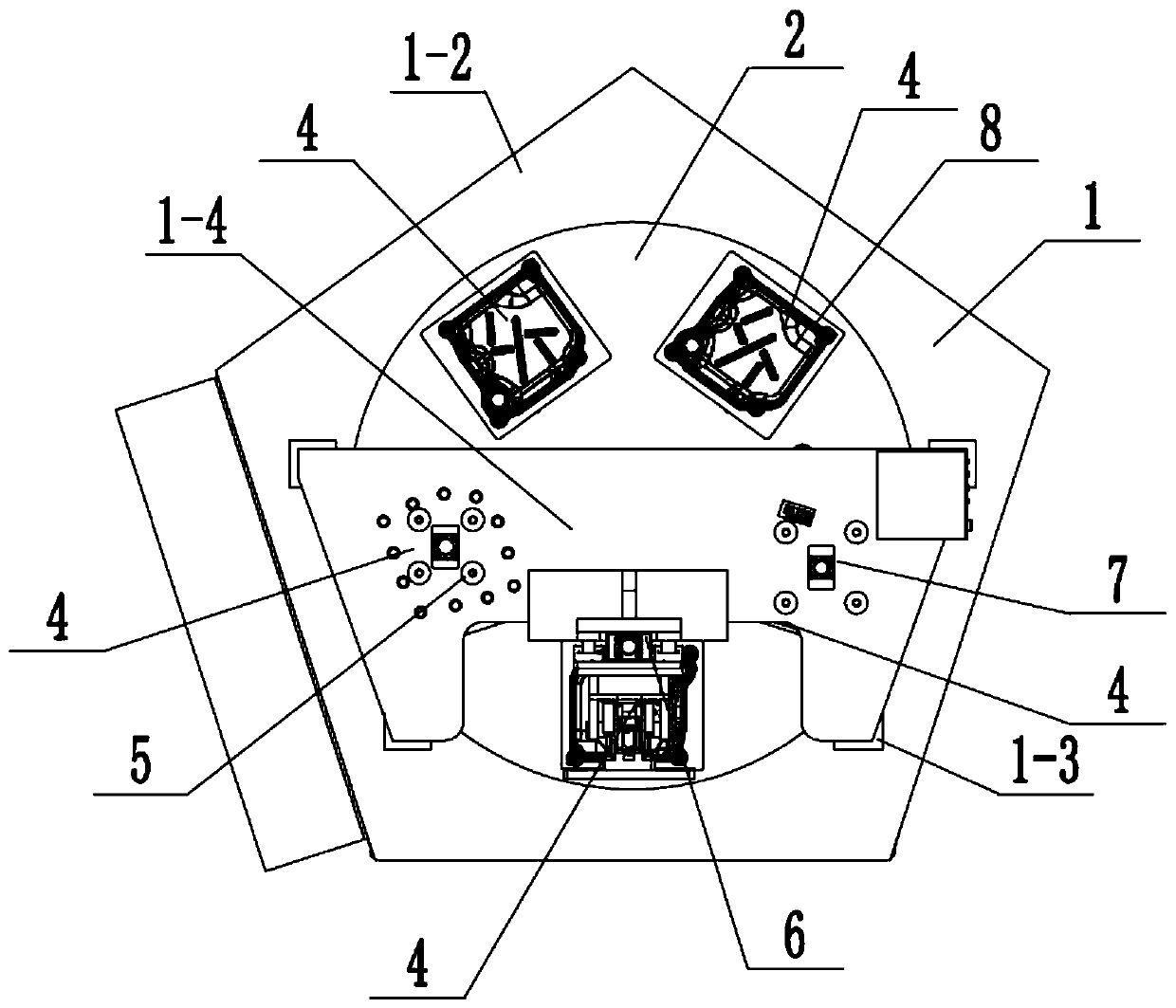
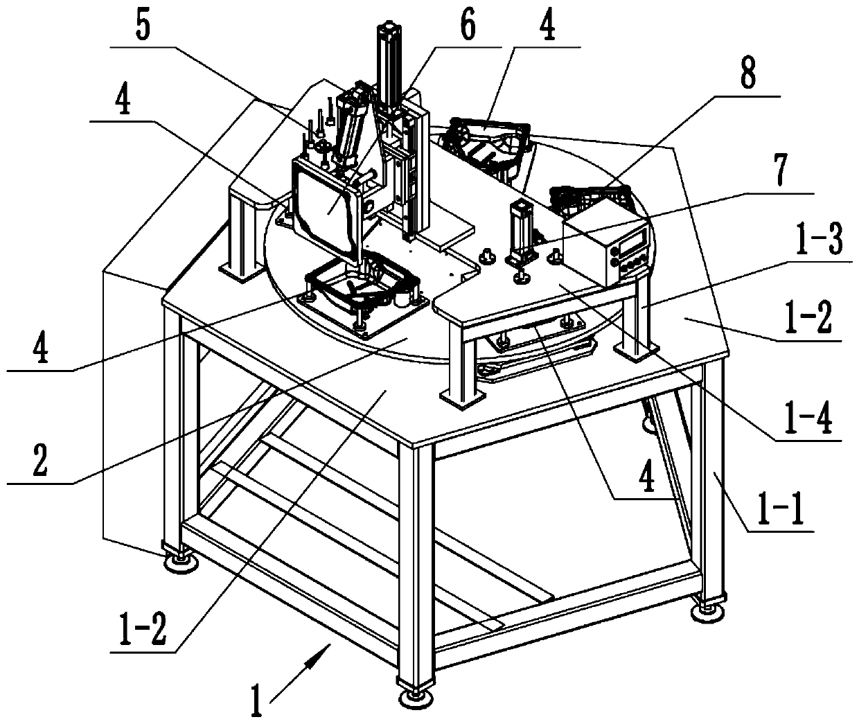
[0047] see Figure 1-16, a gearbox assembly production equipment, which includes a frame 1, a turntable 2, a driving mechanism 3, a dispensing device 5, a gasket loading device 6, a gasket shaping device 7 and a topping device 8.

[0048] See Figure 1-3 , in this embodiment, the frame 1 includes a lower frame 1-1, a middle plate 1-2, an upper frame 1-3 and a top plate 1-4 arranged sequentially from bottom to top.

[0049] The middle plate 1-2 is horizontally arranged and fixed on the upper end of the lower frame 1-1, and the lower end of the lower frame 1-1 is provided with an adjustment foot 1-5.

[0050] The upper frame 1-3 is fixed on the middle plate 1-2, and the top plate 1-4 is arranged horizontally and fixed on the upper end of the upper frame 1-3.

[0051] The turntable 2 is rotatably mounted on the frame 1 .

[0052] Specifically, see Figure 1...


PUM


Abstract

The invention discloses a gearbox assembling production facility. The gearbox assembling production facility is characterized by comprising a machine frame, a rotary table, a driving mechanism, an adhesive dispensing device, a gasket installation device, a gasket reshaping device and a jacking device. The rotary table is installed on the machine frame in a rotatable mode. The driving mechanism comprises a motor and a graduator. The output end of the motor is connected with the rotary table through the graduator. Five gearbox locating tools are arranged on the rotary table and uniformly distributed in the circumferential direction of the rotary table. The adhesive dispensing device, the gasket installation device, the gasket reshaping device and the jacking device correspond to the positions of the four gearbox locating tools in a one-to-one mode and are distributed in sequence. Each gearbox locating tool comprises a tool base plate, a locating pad and multiple locating pins. The gearbox assembling production facility can achieve the purpose of sequentially conducting the feeding and clamping work, the adhesive dispensing work, the gasket installation work, the gasket levelling workand the part discharging work on a gearbox, the occupied space is small, only one-time clamping is required in the whole assembling process, the working efficiency can be improved manyfold, and the production cost is reduced.

Description

technical field [0001] The invention belongs to a gearbox assembly production equipment. Background technique [0002] At present, when the gearbox is assembled, one of the process requirements is: first, glue is dispensed in the gasket ring groove of the cover joint of the gearbox, and then the gasket is put into the gasket ring groove, and the gasket is required to be placed on the gasket ring of the gearbox after assembly. The groove is flat and not upturned. [0003] However, the existing artificial assembly is difficult to overcome the following technical deficiencies: [0004] First, when manual dispensing is used, it is necessary to dispens glue one by one in the gasket ring groove of the cover joint of the gearbox, which has the problems of large position deviation, poor alignment, long operation time and heavy workload; [0005] Second, when the gasket is manually inserted into the gasket ring groove of the gearbox with glue, there will be uneven force in all dire...

Claims


Application Information

Patent Timeline
Patent Type & Authority Applications(China)
IPC IPC(8): B23P21/00B05C7/02B05C13/02
CPCB05C7/02B05C13/02B23P21/006
Inventor 杜鹏罗晓兵黄小秋张娇李松桀
Owner 重庆市綦江区自力汽配有限公司
Why Eureka
Try Eureka