Gas mixing device and engine air inlet mixing structure

A technology of gas mixing device and mixing structure, which is applied in the directions of engine components, machines/engines, charging systems, etc., to achieve the effect of reducing flow rate, improving design and development efficiency, and strengthening mixing effect

Inactive Publication Date: 2019-08-30
ANHUI JIANGHUAI AUTOMOBILE GRP CORP LTD
View PDF10 Cites 1 Cited by
  • Summary
  • Abstract
  • Description
  • Claims
  • Application Information

AI Technical Summary

Problems solved by technology

[0004] The main purpose of the present invention is to propose a gas mixing device and an engine intake mixing structure to optimize the uniformity of exhaust gas and fresh air mixing, so as to solve the problem that the existing mixed intake structure needs trial and error and design optimization

Method used


Image

  • Gas mixing device and engine air inlet mixing structure
  • Gas mixing device and engine air inlet mixing structure
  • Gas mixing device and engine air inlet mixing structure

Examples


Embodiment Construction

[0036] The following will clearly and completely describe the technical solutions in the embodiments of the present invention with reference to the accompanying drawings in the embodiments of the present invention. Obviously, the described embodiments are only part of the embodiments of the present invention, not all of them. Based on the embodiments of the present invention, all other embodiments obtained by persons of ordinary skill in the art without creative efforts fall within the protection scope of the present invention.

[0037] It should be noted that if there is a directional indication (such as up, down, left, right, front, back...) in the embodiment of the present invention, the directional indication is only used to explain the position in a certain posture (as shown in the accompanying drawing). If the specific posture changes, the directional indication will also change accordingly.

[0038] In addition, if there are descriptions involving "first", "second" and ...


PUM


Abstract

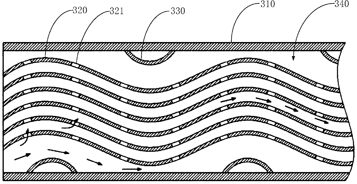
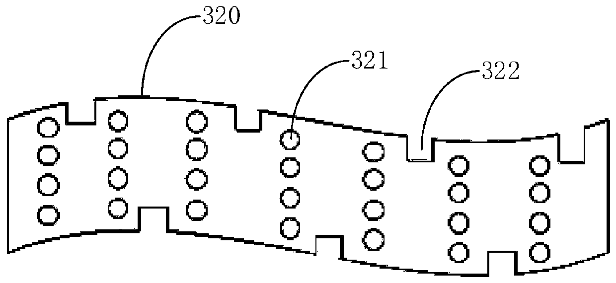
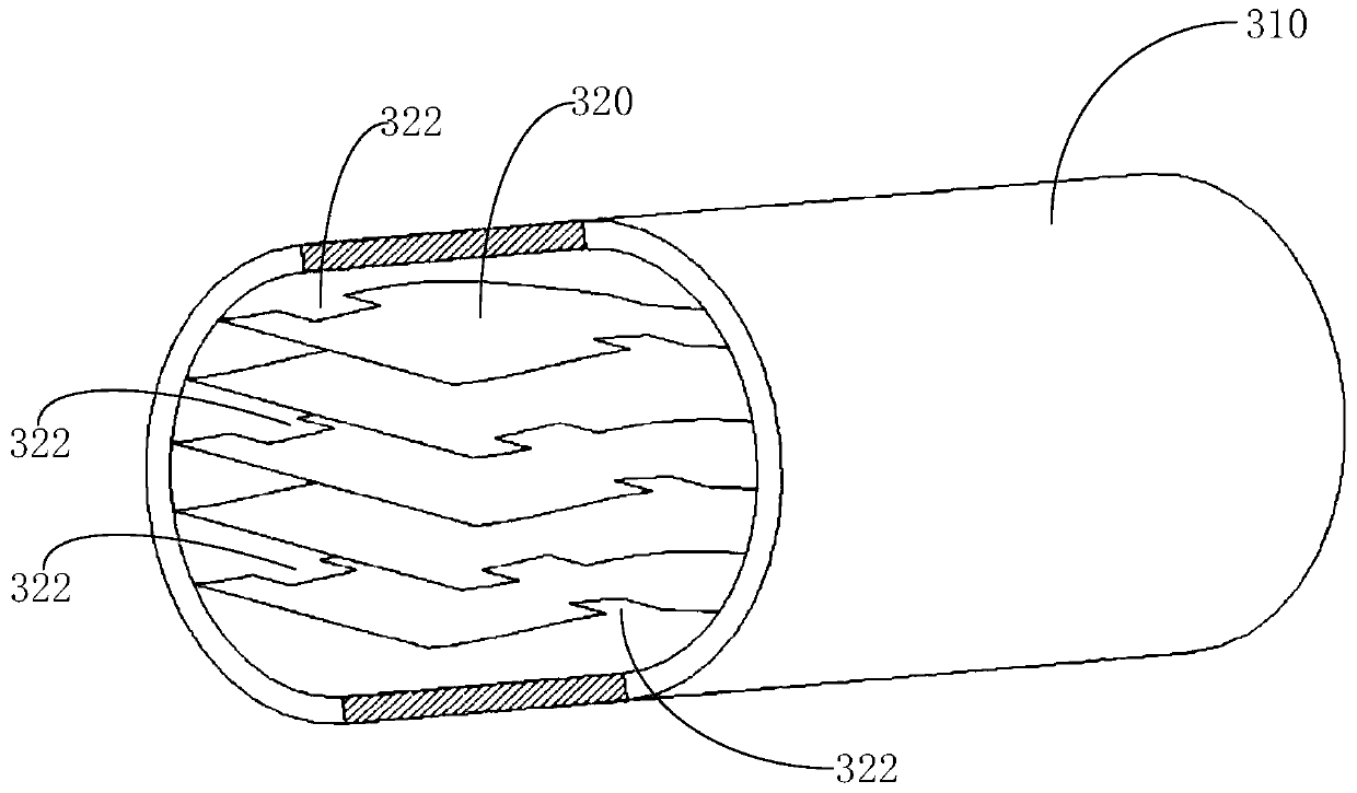
The invention discloses a gas mixing device and an engine air inlet mixing structure. The gas mixing device comprises a mixing main body and gas flow channels, wherein the mixing main body is providedwith an inlet and an outlet for enabling mixed gas to flow in and out; the gas flow channels are formed in the mixing main body and in communication with the inlet and the outlet; at least two gas flow channels are arranged in parallel, and flow guide structures are arranged on the inner side walls of at least one gas flow channels; gas holes penetrate through the flow guide structures, and whenthe mixed gas in the gas flow channels is guided by the flow guide structures, the mixed gas moves from the gas holes to the adjacent gas flow channels; when the mixed gas flows between every two adjacent gas flow channels, radial play is formed so that the mixed gas is mixed more uniformly; and because the mixed gas mainly flows in the axial direction of the main body, the mixed gas can still smoothly flow out from the outlet of the main body. The engine air inlet mixing structure comprises an air inlet main pipe, an exhaust gas recirculation pipe and the gas mixing device.

Description

technical field [0001] The invention belongs to the technical field of engines, and in particular relates to a gas mixing device and an engine intake mixing structure. Background technique [0002] Engine harmful emissions are one of the main sources of air pollution. With the increasing importance of environmental protection, reducing engine harmful emissions is an important challenge facing the current engine industry. Therefore, controlling the emission of harmful engine emissions is the current top priority for all engine designers. Among them, in order to reduce NOx (nitrogen oxides) emissions in engine exhaust, exhaust gas recirculation, as a technical means, can effectively reduce the generation and emission of NOx by diluting the combustible mixture and reducing the maximum combustion temperature of the engine. An important technology used by more and more engines. [0003] In the existing exhaust gas recirculation technology, most of them realize the uniform mixin...

Claims


Application Information

Patent Timeline
Patent Type & Authority Applications(China)
IPC IPC(8): F02M26/19
CPCF02M26/19
Inventor 周波赵真真孙影陈庚王军雷蕾李渊
Owner ANHUI JIANGHUAI AUTOMOBILE GRP CORP LTD
Why Eureka
Try Eureka