
Crawling driving system of artillery barrel robot

A technology for artillery barrels and drive systems, which is applied to motor vehicles, weapon accessories, and weapon testing. It can solve the problems of high assembly difficulty, inability to guarantee quantification, and low accuracy. It can maintain axial movement and be easy to disassemble and maintain. , the effect of improving accuracy

Inactive Publication Date: 2019-08-30
TIANJIN UNIV
View PDF6 Cites 2 Cited by
  • Summary
  • Abstract
  • Description
  • Claims
  • Application Information

AI Technical Summary

Problems solved by technology

[0004] The existing domestic technology often carries a camera into the pipeline by holding a long pole, or uses an endoscope to measure. This kind of measurement can only be called qualitative measurement. The accuracy of determining the approximate degree of flaws of the object to be measured through qualitative measurement is very low, and requires a lot of manpower
The most important thing is that the specific axial and circumferential positions of the measuring device cannot be guaranteed, neither image data nor point cloud data can guarantee quantitative
For simple viewing purposes only
[0005] There are also researchers who have improved the movement ability of the structure inside the pipe wall through complex mechanical structures such as planetary gears, which can easily overcome the smooth rifling of the pipe, but the assembly is very difficult and the stability is not good, and the requirements for the pipe wall environment are very high. High, the stability and accuracy are not good in narrow and long pipes, and it is difficult to play a big role

Method used


Image

  • Crawling driving system of artillery barrel robot
  • Crawling driving system of artillery barrel robot
  • Crawling driving system of artillery barrel robot

Examples


Embodiment Construction

[0024] The present invention will be further described below in conjunction with accompanying drawing.

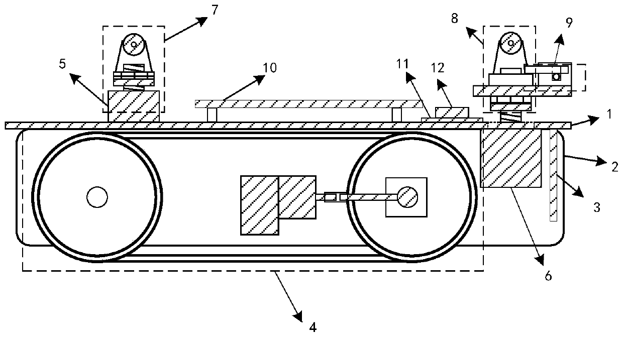
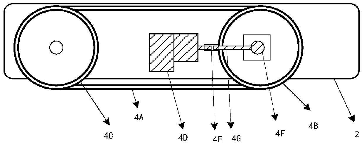
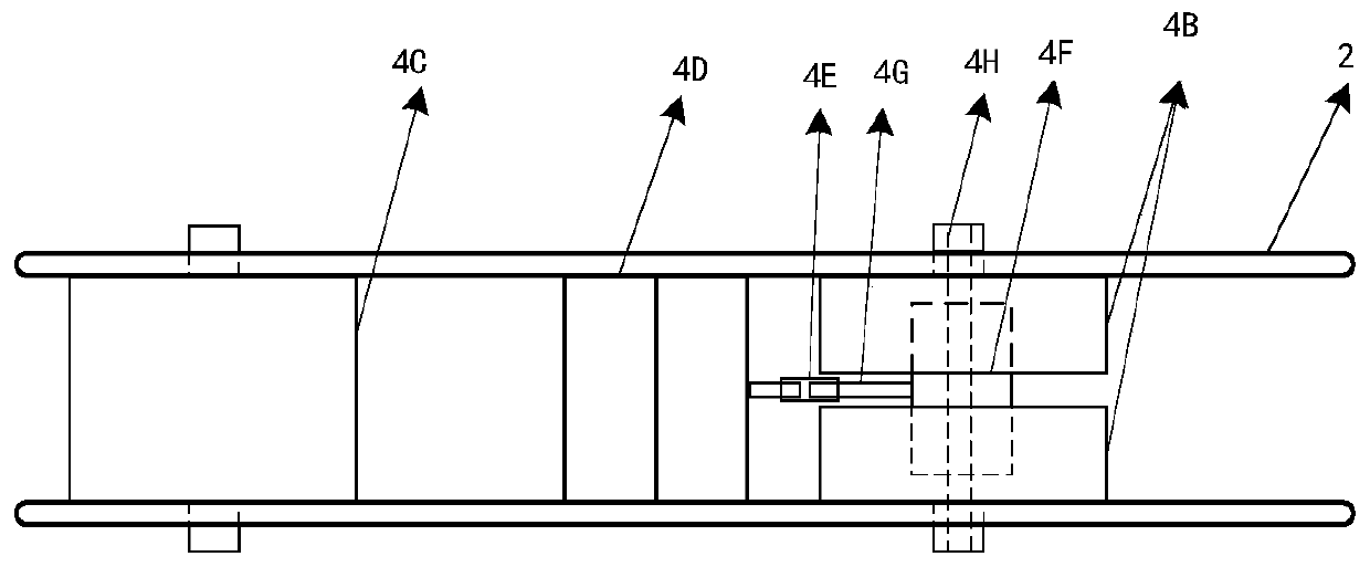
[0025] as attached figure 1 As shown, the artillery barrel robot crawling drive system of the present invention includes two vertical support plates 2 arranged in parallel intervals along the vertical direction, and the left and right sides of a horizontal top plate 1 arranged in the horizontal direction are supported and fixed on the left and right sides respectively. On the two vertical support plates 2 mentioned above. A connection plate 3 is fixed at the front end between the two vertical support plates 2, and the connection plate is used to install a measurement subsystem for measuring the shape information of the gun barrel tube wall. The measurement subsystem adopts the existing Systems, such as small industrial cameras and mechanical components or laser displacement sensors and their mechanical components.

[0026] A pulley shaft arranged in the horizontal directi...


PUM


Abstract

The invention discloses a crawling driving system of an artillery barrel robot. The crawling driving system of the artillery barrel robot can push a measuring system to crawl, record and correct the circumferential pose, and meanwhile, the pipe wall pressure can be adjusted so as to guarantee the advancing stability. The design implementation of the system comprises a main control unit, a crawlingunit, a pose adjusting unit and a pressure adjusting unit. A barrel robot enters a narrow pipeline for inner wall measurement under the control of the main control unit, the pressure of the pipe wallof the system in the pipeline and the states comprising the circumferential deflection of the system and the like are obtained according to the data of a pressure sensor and an inclination angle sensor, then the pose adjusting unit and the pressure adjusting unit are controlled, and the pose stability and continuous crawling of the body barrel robot in the narrow and long pipeline with complex environment can be ensured. The crawling driving system has the characteristics of simple assembly, good stability and wide application, and can be adapted to the pipelines with different pipe diametersand different internal environments.

Description

technical field [0001] The invention relates to a crawling drive system, in particular to a crawling drive system for a gun barrel robot. Background technique [0002] Artillery has the advantages of low price and mature technology in military industry, and plays an important role in military industry weapons. Moreover, due to the special features of the military industry, it is even more necessary to ensure the reliability and safety of the pipeline. The inner wall of the pipeline must be measured regularly to scientifically and quantitatively determine the quality and defect loss of the pipeline. However, the inner bore of the artillery barrel has the characteristics of long length (about 10 meters), small diameter (diameter of 100 mm), and complex internal structure (with rifling and flaws). Compared with qualitative measurement, it is more required to be able to measure the pipeline quantitatively and accurately. Pipeline robots designed for measurement are generally ...

Claims


Application Information

Patent Timeline
IPC IPC(8): F41A31/02B62D55/02
CPCB62D55/02F41A31/02
Inventor 张尹馨王星宇黄战华岳富军张光
Owner TIANJIN UNIV
Learn More