Distance measuring method and depth camera

A distance measurement and distance technology, applied in the optical field, can solve the problems of increasing power consumption, decreasing accuracy, extending the pulse width of modulation and demodulation, etc., to achieve the effect of low test power consumption and high test accuracy

Active Publication Date: 2019-08-30
SHENZHEN ORBBEC CO LTD
View PDF13 Cites 10 Cited by
  • Summary
  • Abstract
  • Description
  • Claims
  • Application Information

AI Technical Summary

Problems solved by technology

[0004] In view of this, the embodiment of the present invention provides a distance measurement method to solve the technical problems that the existing I-TOF technology needs to extend the modulation and demodulation pulse width when performing long-distance testing, resulting in increased power consumption and decreased accuracy.

Method used


Image

  • Distance measuring method and depth camera
  • Distance measuring method and depth camera
  • Distance measuring method and depth camera

Examples


Embodiment Construction

[0032] In the following description, specific details such as specific system structures and technologies are presented for the purpose of illustration rather than limitation, so as to thoroughly understand the embodiments of the present invention. It will be apparent, however, to one skilled in the art that the invention may be practiced in other embodiments without these specific details. In other instances, detailed descriptions of well-known systems, devices, circuits, and methods are omitted so as not to obscure the description of the present invention with unnecessary detail.

[0033] In order to illustrate the technical solutions of the present invention, specific examples are used below to illustrate.

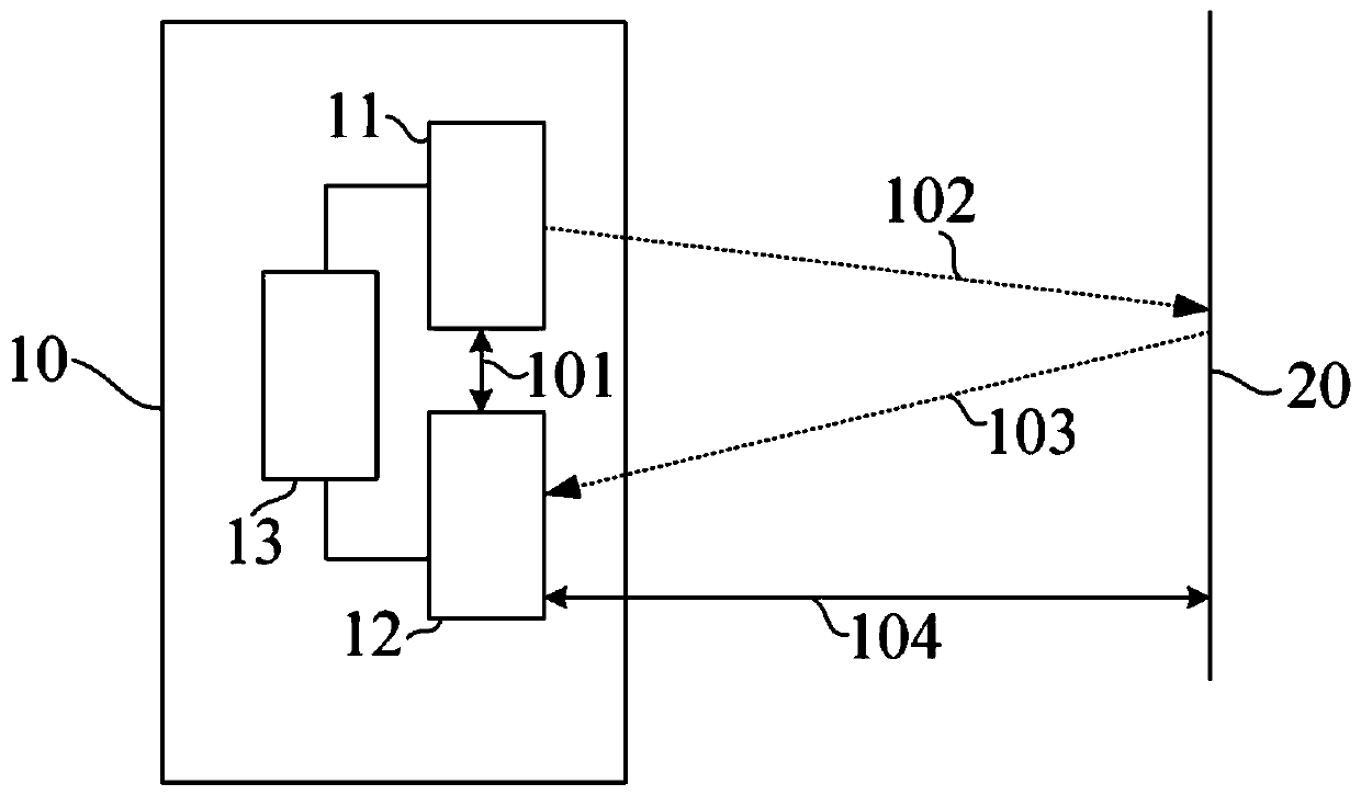
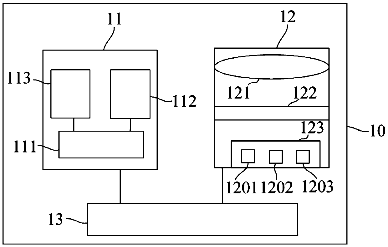
[0034] figure 1 It is a schematic diagram of a depth camera 10 provided by an embodiment of the present invention. The depth camera is a TOF depth camera, including a transmitting module 11 , a receiving module 12 and a control module 13 , and the control module 13 is...


PUM


Abstract

The invention is applied to the technical field of optics, and provides a distance measuring method and a depth camera. The distance measuring method comprises the following steps: transmitting an optical signal to an object to be measured; receiving the optical signal reflected by the object to be measure through a receiving module, wherein the receiving module comprises a plurality of signal collecting units, the timing sequences of the plurality of signal collecting units are different, and each signal collecting unit has at least two sets of collection signals with different frequencies inone exposure time; and calculating the flight time of the optical signal. By setting a plurality of taps in the depth camera, and controlling the collecting timing sequences of the plurality of collecting units through the control module, each tap has at least two sets of collection signals with different frequencies in one exposure time; therefore, the contradiction of in test scheme in the prior art that the pulse width is proportional to the test distance and power consumption and is negatively correlated with the test accuracy is got rid of, and the measurement distance is no longer limited by the pulse width; therefore, lower test power consumption and higher test accuracy is maintained while achieving a farther test distance.

Description

technical field [0001] The invention belongs to the field of optical technology, in particular to a distance measurement method and a depth camera. Background technique [0002] ToF (Time-of-Flight, time-of-flight) is a technology that achieves precise distance measurement by measuring the time-of-flight of light. The currently commonly used TOF depth camera adopts an I-TOF (Indirect-TOF) technology, which emits a beam of periodically modulated laser light in time series to the surface of the object through a laser emitting device, and the reflected light generates a time series relative to the incident light. The I-TOF technology measures the time of flight of light by measuring the test data of different taps, and further realizes the distance measurement. [0003] According to different modulation and demodulation modes, the time-of-flight technology can be divided into a continuous wave (Continuous Wave, CW) modulation and demodulation mode and a pulse modulation (Pulse...

Claims


Application Information

Patent Timeline
Patent Type & Authority Applications(China)
IPC IPC(8): G01S17/48
CPCG01S17/48Y02A90/30
Inventor 胡小龙
Owner SHENZHEN ORBBEC CO LTD
Why Eureka
Try Eureka