Handheld angle drill

A hand-held, angle-drilling technology, used in portable drilling rigs, drilling/drilling equipment, components of boring machines/drilling machines, etc., can solve the problem of reducing the service life of hand-held angle drills, increasing the difficulty of assembly of drive mechanisms, planetary gear trains and drill bits, The problem of crowded space of the hand-held angle drill head can reduce assembly difficulties, improve driving efficiency, and simplify the transmission mechanism.

Inactive Publication Date: 2019-09-03
ZHEJIANG KAICHUANG ELECTRICAL CO LTD
View PDF4 Cites 1 Cited by
  • Summary
  • Abstract
  • Description
  • Claims
  • Application Information

AI Technical Summary

Problems solved by technology

[0004] Although the existing hand-held angle drills can achieve the purpose of miniaturization by designing the shell structure and internal drive mechanism, the drive mechanism of the existing hand-held angle drills often transmits the driving force to the drill bit through the planetary gear train, and the planetary gear train is due to only It can achieve the effect of transmitting the driving force in the horizontal direction. Therefore, the planetary gear system has higher requirements on the distribution position of the driving mechanism and the drill bit. The head of the angle drill, this distribution method not only makes the head space of the hand-held angle drill crowded, but also increases the difficulty of assembling the drive mechanism, planetary gear train and drill bit. Further, the crowded drive mechanism, planetary gear train And the drill bit will also affect the transmission efficiency of the drive mechanism under the combined action of axial force and circumferential force, and even the axial force of the drill bit will be transmitted to the drive mechanism through the planetary gear train, causing the drive mechanism to fail, which greatly reduces the holding angle. drill life

Method used


Image

  • Handheld angle drill
  • Handheld angle drill
  • Handheld angle drill

Examples


Embodiment Construction

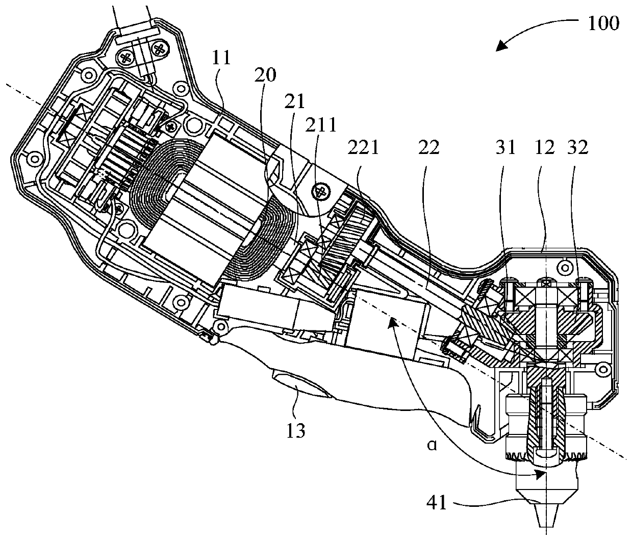
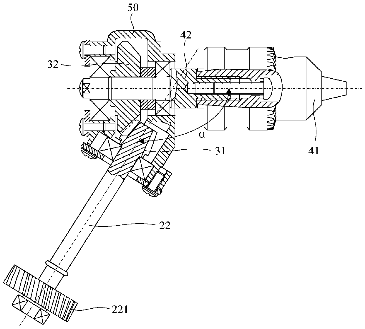
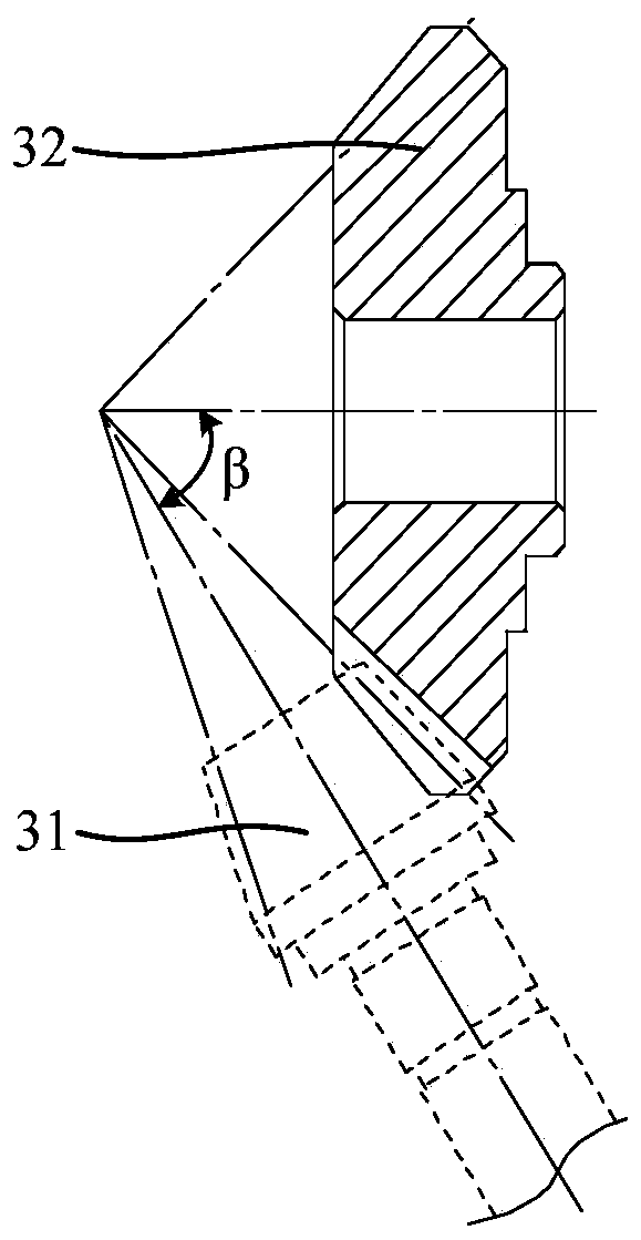
[0028] Exemplary embodiments of the present disclosure will be described in more detail below with reference to the accompanying drawings. Although exemplary embodiments of the present disclosure are shown in the drawings, it should be understood that the present disclosure may be embodied in various forms and should not be limited by the embodiments set forth herein. Rather, these embodiments are provided for more thorough understanding of the present disclosure and to fully convey the scope of the present disclosure to those skilled in the art. It should be noted that the application of the bevel gear train of the present invention and the arrangement of the bevel gear train to the hand-held angle drill is only a preferred embodiment, and is not a limitation of the scope of application of the bevel gear train of the present invention. For example, the bevel gear train and bevel gear train of the present invention The arrangement of the gear train can also be used in other de...


PUM


Abstract

The invention relates to the technical field of electric drills, in particular to a handheld angle drill. The invention aims to solve the technical problems that a transmission mechanism of the handheld angle drill is complex in structure and low in transmission efficiency. For the purpose, the invention provides a handheld angle drill. The handheld angle drill comprises a housing, a driving device, a bevel gear train and a drill bit assembly; the housing comprises a grip housing part and a drill bit housing part; and the driving device is arranged in the grip housing part, the drill bit assembly is arranged at the drill bit housing part and extends out of the drill bit housing part, and the driving device drives the drill bit assembly through the bevel gear train. The driving device in the handheld angle drill drives the drill bit assembly through the bevel gear train, not only the transmission mechanism of the handheld angle drill is simplified, but also the transmission efficiency of the driving device is improved; and meanwhile, the bevel gear train can share part of the axial force of the drill bit assembly, so that the phenomenon that the axial force of the drill bit assemblydirectly acts to the driving device to damage the driving device is reduced.

Description

technical field [0001] The invention relates to the technical field of electric drills, in particular to a hand-held angle drill. Background technique [0002] This section provides background information related to the present disclosure only and is not necessarily prior art. [0003] Compared with the electric drill, the handheld angle drill has a unique shell structure and internal drive mechanism. The unique shell enables the handheld angle drill to be used for drilling operations in narrow spaces. The unique internal drive mechanism can improve the structure of the handheld angle drill. The overall volume of the angle drill makes the handheld angle drill suitable for narrow working spaces. [0004] Although the existing hand-held angle drills can achieve the purpose of miniaturization by designing the shell structure and internal drive mechanism, the drive mechanism of the existing hand-held angle drills often transmits the driving force to the drill bit through the pl...

Claims


Application Information

Patent Timeline
Patent Type & Authority Applications(China)
IPC IPC(8): B23B45/02B23B47/06B23Q5/10
CPCB23B45/02B23B47/00B23Q5/10
Inventor 丁金福杨金伟刘光源
Owner ZHEJIANG KAICHUANG ELECTRICAL CO LTD
Why Eureka
Try Eureka