A layered steam injection pipe string and method under general sand control in straight inclined wells for thermal recovery

A layered steam injection and sand control technology, applied in the direction of production fluid, earthwork drilling, wellbore/well components, etc., can solve the problems of dryness difference, waste of heat energy, inability to realize layered steam injection, etc., to overcome steam absorption Small ratio, improved injection dryness, simple and compact structure

Active Publication Date: 2021-07-02
CHINA PETROLEUM & CHEM CORP +1
View PDF6 Cites 0 Cited by
  • Summary
  • Abstract
  • Description
  • Claims
  • Application Information

AI Technical Summary

Problems solved by technology

This device only realizes layered steam injection under the condition of layered sand control, and cannot realize layered steam injection in general sand control wells. At the same time, due to the difference in steam injection pressure of each layer, the dryness of steam injection in each layer is different, resulting in some waste of heat
[0005] To sum up, the current layered steam injection technology and method are mainly suitable for chemical sand control or layered sand control thermal recovery steam injection wells, and layered steam injection of thermal recovery vertically inclined wells for general sand control cannot be realized

Method used


Image

  • A layered steam injection pipe string and method under general sand control in straight inclined wells for thermal recovery
  • A layered steam injection pipe string and method under general sand control in straight inclined wells for thermal recovery
  • A layered steam injection pipe string and method under general sand control in straight inclined wells for thermal recovery

Examples


Embodiment Construction

[0030] The following will clearly and completely describe the technical solutions in the embodiments of the present invention with reference to the accompanying drawings in the embodiments of the present invention. Obviously, the described embodiments are only some, not all, embodiments of the present invention. Based on the embodiments of the present invention, all other embodiments obtained by persons of ordinary skill in the art without making creative efforts belong to the protection scope of the present invention.

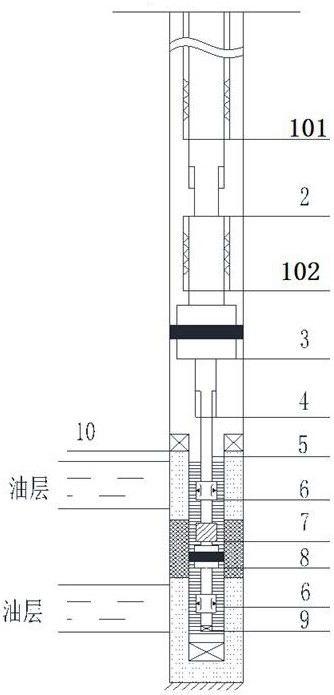
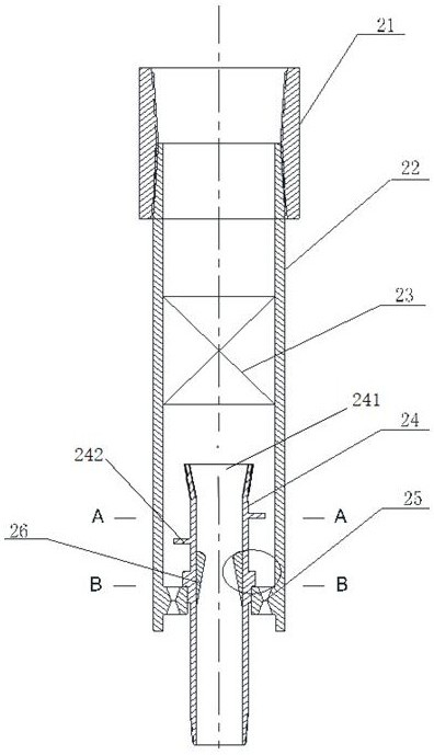
[0031] see Figure 1 to Figure 6 , the present invention provides a technical solution: the steam injection system is used for layered steam injection of two or more oil layers under general sand control conditions. In this embodiment, the case of two oil layers is used as an example for illustration. The upper heat-insulated oil pipe 101 adopts high-vacuum heat-insulated oil pipe or new airgel heat-insulated oil pipe. The above two types of heat-insulated oil...


PUM


Abstract

The invention discloses a layered steam injection pipe string and method under general sand control of straight inclined wells in thermal production. There are at least two dispensers, which respectively correspond to different oil layers, and an interlayer packer is arranged between two of the dispensers; A phase separator, the liquid phase separator includes an outer tube and an inner tube, the inner wall of the outer tube is provided with swirl vanes, the upper half of the inner tube enters the interior of the outer tube, and the inner tube is located below the swirl vanes, The inner wall of the outer tube is also provided with an axial liquid phase nozzle, the liquid phase nozzle is located in the annular space formed between the outer tube and the inner tube, and the inner wall of the inner tube is provided with a gas phase critical flow nozzle. The invention utilizes the density difference between the gas and liquid phases to establish a liquid phase separation with a certain thickness between the sand control pipe string and the casing, so as to ensure the effective isolation of the upper and lower oil layers under general sand control conditions.

Description

technical field [0001] The invention relates to a steam injection process for thermal recovery of heavy oil produced in an oil field, in particular to a layered steam injection pipe column and a method for thermal recovery straight inclined well under general sand control. Background technique [0002] Thermal oil recovery is one of the important methods for the development of heavy oil reservoirs, and steam huff and puff and steam flooding are the most widely used. More than 80% of the heavy oil in Shengli Oilfield is multi-layered reservoirs. General steam injection is generally used in the development of vertically inclined wells for thermal recovery. The difference in steam absorption between layers is large, and the conflict between layers is prominent. Especially when the physical parameters of the upper layer are obviously due to the lower layer, the steam overlapping causes the upper layer to have high dryness, and the good physical parameters cause the upper layer t...

Claims


Application Information

Patent Timeline
Patent Type & Authority Patents(China)
IPC IPC(8): E21B43/24E21B33/12
CPCE21B33/12E21B43/24
Inventor 赵晓谢志勤戴宇婷王超张鹏刘岩何旭梁伟
Owner CHINA PETROLEUM & CHEM CORP
Why Eureka
Try Eureka