Support device of large-scale vertical axis wind turbine and wind turbine

A technology of supporting device and vertical axis, applied in the fields of wind energy utilization, wind machinery and wind power generation, can solve problems such as unfavorable development of large or super-large wind turbines, large-scale wind power, limiting the rotation radius of the wind wheel and the height of the wind wheel, etc., to achieve optimization The main shaft stress structure, the effect of expanding the bearing area and reducing the quality of the wind rotor

Inactive Publication Date: 2019-09-03
孟英志
View PDF3 Cites 4 Cited by
  • Summary
  • Abstract
  • Description
  • Claims
  • Application Information

AI Technical Summary

Problems solved by technology

Its shortcoming is that the external support of the wind wheel or the height of the blades are all limited within the barrel-shaped steel frame, which greatly limits the rotation radius of the wind wheel and the height of the wind wheel, which is not conducive to the developm

Method used


Image

  • Support device of large-scale vertical axis wind turbine and wind turbine
  • Support device of large-scale vertical axis wind turbine and wind turbine
  • Support device of large-scale vertical axis wind turbine and wind turbine

Examples


Embodiment 1

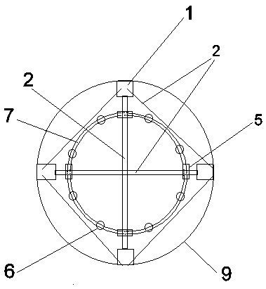
[0071] Such as Figure 1-5 As shown, the support structure of the large vertical axis fan according to the present invention or the invention includes an annular horizontal track 7, a track support column 6 and a foundation 4, the track support column 6 is fixedly installed on the foundation 4, and the annular horizontal track 7 is fixedly installed on the track support On the column 6, rollers 5 are arranged on the annular horizontal track 7, and the rollers 5 are installed on the supporting columns 1 or connecting wings 2, and between two or four supporting columns 1, there are a plurality of connecting wings 2 or / and inclined The pull wings 3 are connected; the two or four support columns and at least two connecting wings 2 or inclined stay wings 3 form an integral member in a ring. The overall member in the ring can freely rotate on the circular horizontal track 7 through the roller 5 .

[0072] In the present invention or in the invention, the foundation 4 is located on ...

Embodiment 2

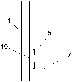
[0082] Such as Figure 6 , 7 As shown, an upper support wing 13 and a lower support wing 14 are installed on the support column 1 , one end of the upper or / and lower support wing is connected to the support column 1 , and the other end is connected to the blade 12 .

[0083]Between the support column 1, the upper and lower support wings 13, 14 and the blades 12, there are connecting wings 2 or / and obliquely-stayed wings 3 connected, the support column 1, the upper and lower support wings 13, 14, the blades 12 and the connecting wing 2 or the inclined-stayed wing 3 form an integral component outside the ring.

[0084] Such as Figure 6 As shown, there is a diagonally-stayed wing 3 connected between the upper end of the support column 1 and the upper end of the integral member outside the ring; the upper end of the integral member outside the ring refers to the upper support wing 13 here. Between the lower end of the support column 1 and the lower end of the integral member o...

Embodiment 3

[0089] Such as Figure 8 as shown, Figure 8 It is a partial plan view of the connection structure between the present invention or the invention's supporting wing 15 and the lower supporting wing 14; the supporting wing 15 is arranged on the top of the annular horizontal track 7, and intersects and connects with the bottom connecting wing 2 of the integral member in the ring, the supporting wing 15 is provided with a roller 5 below, and the roller 5 is supported on the circular horizontal rail 7 and can rotate freely. At both ends of the supporting wing 15, there is respectively a diagonally-stayed wing 3 and a lower supporting wing 14 close to the direction of the blade. Connected at one end. The inclined-stayed wing 3 plays a role of supporting or tightening the lower supporting wing 14 .

[0090] In order to simplify the description, this embodiment only draws a partial top view of the connection structure between the two supporting wings 15 and the lower supporting wing...


PUM


Abstract

The invention provides a support device of a large-scale vertical axis wind turbine and a wind turbine. The support device comprises at least one ring-shaped horizontal track and track support components; the at least one ring-shaped horizontal track is fixedly arranged on the track support components. The support device is characterized by further comprising chord support wings, at least two blades and a lower support wing, an upper support wing, a support pillar and a connecting wing or stayed swings corresponding to each blade; and the lower support swings, the upper support wings, the support pillars and the connecting wings or the stayed wings are connected with each other to form an integral component. The support device has the beneficial effects that a main shaft no long bears thegravity and the radial force of a wind wheel; the stress structure of the main shaft is optimized; only the turning moment of the wind wheel is transmitted; meanwhile, the wind sweeping radius of thewind wheel is increased; and the use amount of a support material is greatly reduced, so that the weight of the wind wheel is reduced, and the cost is reduced.

Description

technical field [0001] The invention belongs to the technical field of wind energy utilization, and is especially applicable to the technical field of wind power machinery and wind power generation, and is used for supporting a vertical axis wind power generator and a wind wheel of the wind power generator. Background technique [0002] Vertical axis fan is the abbreviation of vertical axis wind turbine, which refers to a wind turbine whose rotation axis is perpendicular to the ground or the direction of incoming flow. For the development of wind power generation at altitudes above 150 meters, or super-large wind power generators, vertical axis wind power generators have huge advantages. Vertical axis wind power generators can install the generator system on the ground, and use the main shaft of the fan to transmit the wind energy received by the high-altitude wind rotor. Converted to electrical energy by the ground generator system. However, due to the heavy weight of the ...

Claims


Application Information

Patent Timeline
IPC IPC(8): F03D13/20F03D9/25F03D3/06F03D3/00
CPCF03D3/005F03D3/064F03D9/25F03D13/20F03D15/00Y02E10/728Y02E10/74
Inventor 孟英志
Owner 孟英志
Why Eureka
Try Eureka