
Small-sized farmland irrigation device

A farmland irrigation and small-scale technology, applied in watering devices, agriculture, gardening, etc., can solve problems such as maintenance difficulties, large pressure differences, and processing difficulties, and achieve the effects of reducing maintenance difficulty, reducing work pressure, and reducing production costs

Inactive Publication Date: 2019-09-06
HENAN UNIV OF ANIMAL HUSBANDRY & ECONOMY
View PDF7 Cites 1 Cited by
  • Summary
  • Abstract
  • Description
  • Claims
  • Application Information

AI Technical Summary

Problems solved by technology

The disadvantage of this method is that the pressure difference between the inlet end and the end of the pipeline of hundreds of meters will be large due to the loss of the nozzle, and the flow rate of ordinary micro-spray heads is proportional to the pressure. The greater the pressure, the greater the flow rate, which will cause The amount of water obtained by the front-end crops is inconsistent with the water and nutrients obtained by the middle and end, which in turn affects the crop yield and quality
[0010] 1. In mountainous areas, due to terrain and other reasons, the location of the water source is often high, and there is no need to use pressurization technology for pressure compensation, and the terrain in the mountainous area is uneven, and the rotating nozzle cannot spray water to high places, so the micro-sprinkler sprinkler is not suitable for mountainous areas;
[0011] 2. The impact of the pressure compensation chip is relatively large. Every time the nozzle is switched on and off, the pressure compensation chip will be deformed repeatedly and greatly, and the deformation pressure is completely applied to the pressure compensation chip, resulting in a low life of the pressure compensation chip;
[0012] 3. The internal structure is integrally formed, which is difficult to process, high production cost, and difficult to maintain

Method used


Image

  • Small-sized farmland irrigation device
  • Small-sized farmland irrigation device
  • Small-sized farmland irrigation device

Examples


Embodiment Construction

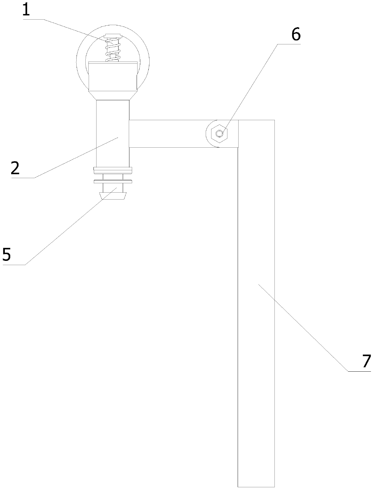
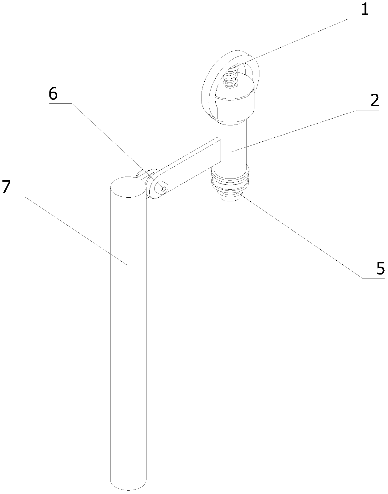
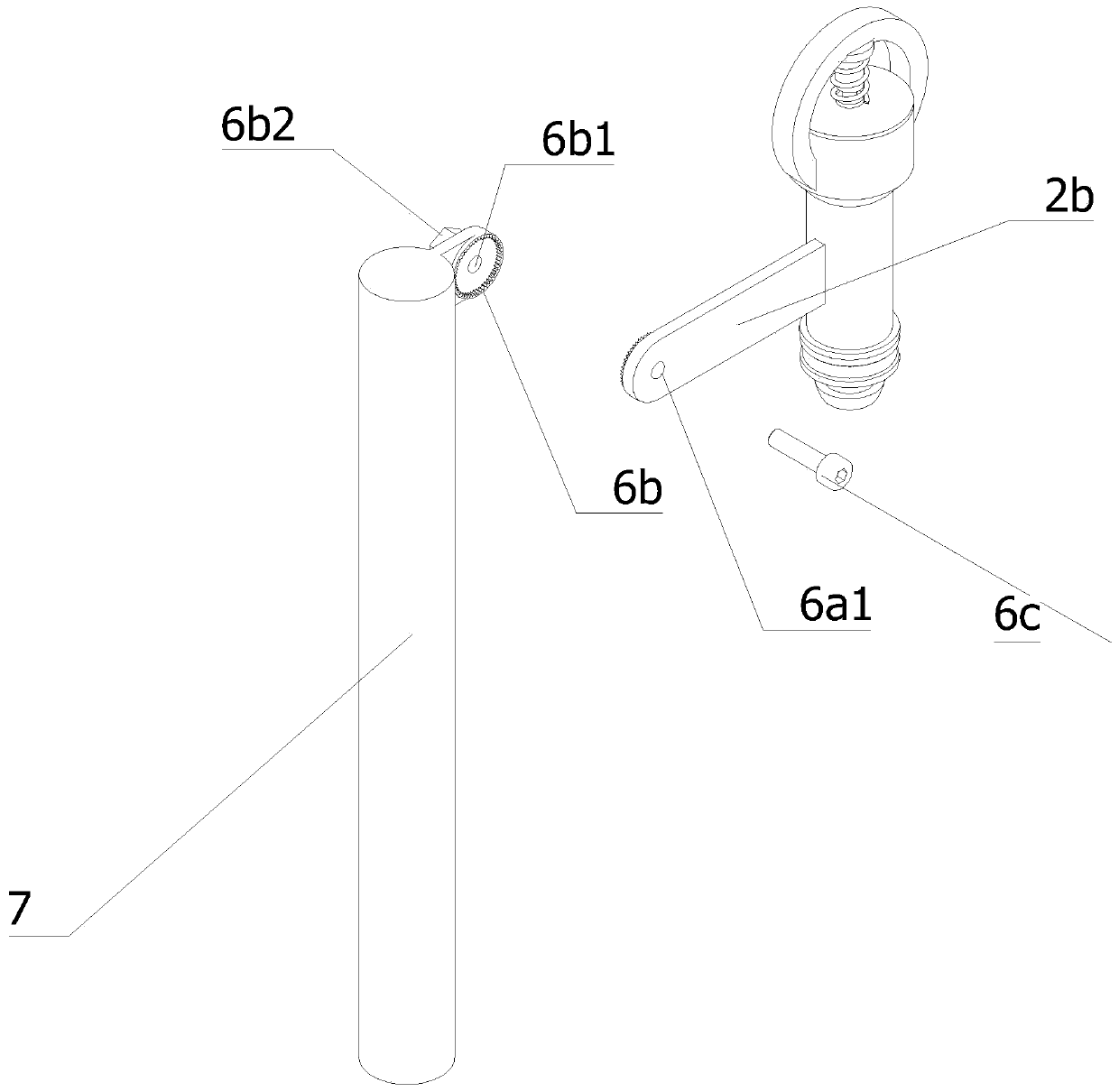
[0058] The technical solutions of the present invention will be further described below in conjunction with the accompanying drawings and through specific implementation methods.

[0059] Wherein, the accompanying drawings are only for illustrative purposes, showing only schematic diagrams, rather than physical drawings, and should not be construed as limitations on this patent; in order to better illustrate the embodiments of the present invention, some parts of the accompanying drawings will be omitted, Enlargement or reduction does not represent the size of the actual product; for those skilled in the art, it is understandable that certain known structures and their descriptions in the drawings may be omitted.

[0060] In the drawings of the embodiments of the present invention, the same or similar symbols correspond to the same or similar components; , "inner", "outer" and other indicated orientations or positional relationships are based on the orientations or positional ...


PUM


Abstract

The invention relates to the technical field of irrigation devices, in particular to a small-sized farmland irrigation device. The small-sized farmland irrigation device comprises a rotary micro sprayhead, a pressure reducing pipeline, a capillary pipe joint, an angle regulator and a vertical rod. The vertical rod is vertically inserted into a farmland, and the pressure reducing pipeline is fixedly connected with the vertical rod through the angle regulator; the capillary pipe joint is fixedly mounted at the bottom end of the pressure reducing pipeline, and the rotary micro spray head is fixedly mounted at the top end of the pressure reducing pipeline; the capillary pipe joint, the pressure reducing pipeline and a water path of the rotary micro spray head are sequentially communicated from bottom to top; and a high-pressure pressure reducing mechanism and a low-pressure pressure reducing mechanism are mounted in the pressure reducing pipeline. The irrigation device is suitable for mountainous areas and terraces, wide in fed water pressure range, long in service life, low in production cost and low in maintenance difficulty.

Description

technical field [0001] The invention relates to the technical field of irrigation devices, in particular to a small farmland irrigation device. Background technique [0002] Technical measures for replenishing the water needed by crops. In order to ensure the normal growth of crops and obtain high and stable yields, crops must be supplied with sufficient water. Under natural conditions, often due to insufficient precipitation or uneven distribution, the water requirements of crops cannot be met. Therefore, artificial irrigation must be carried out to make up for the deficiency of natural rainfall. [0003] Irrigation, i.e. irrigating the land with water. The principle of irrigation is that the amount of irrigation, the frequency of irrigation and the time should be determined according to the water demand characteristics of medicinal plants, growth stages, climate, and soil conditions, and should be timely, appropriate, and rational irrigation. The types mainly include p...

Claims


Application Information

Patent Timeline
Patent Type & Authority Applications(China)
IPC IPC(8): A01G25/02A01G25/16
CPCA01G25/02A01G25/16
Inventor 朱熙宁
Owner HENAN UNIV OF ANIMAL HUSBANDRY & ECONOMY
Learn More