
Induction heat treatment equipment for caterpillar chain links

A technology of induction heat treatment and crawler chain, which is applied in the field of chain rail link processing equipment, can solve problems such as non-universal use, need for improvement, impact on chain rail link production and quality stability, etc., to achieve reduced labor intensity, low processing and production difficulty, Avoid the time-consuming effect of walking around

Pending Publication Date: 2019-09-06
钢客履带(江苏)有限公司
View PDF0 Cites 2 Cited by
  • Summary
  • Abstract
  • Description
  • Claims
  • Application Information

AI Technical Summary

Problems solved by technology

However, since the left and right chain rail sections are symmetrical in shape, the sensors of the left and right chain rail sections are also symmetrical in shape. Since the angles and sizes of the two sides of the chain rail section tread are not exactly the same, although the shapes of the left and right sensors are very similar, the direction of the equipment interface, etc. The problem is generally not universal
Therefore, in the conventional production process, it is often necessary to switch between the left and right chain rail link processing, which requires frequent replacement of sensors and positioning clamping devices, which will affect the chain rail link production and quality stability, and needs to be improved.

Method used


Image

  • Induction heat treatment equipment for caterpillar chain links
  • Induction heat treatment equipment for caterpillar chain links

Examples


Embodiment Construction

[0022] In order to make the technical solutions and advantages of the present invention clearer, the present invention will be further described in detail below in conjunction with the accompanying drawings.

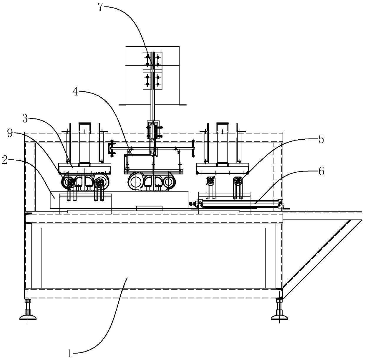
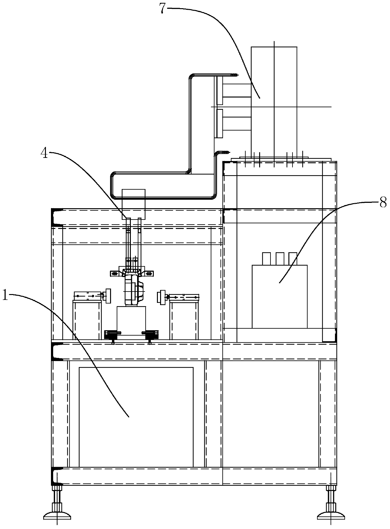
[0023] like figure 1 As shown, a kind of induction heat treatment equipment for track chain link, including equipment machine tool 1. The machine tool 1 is provided with an induction heat treatment mechanism 4 , a cooling mechanism 3 located at the left and right ends of the induction heat treatment mechanism 4 , and a fixed transmission plate 2 for fixing the chain rail link body 9 . The left and right ends of the fixed transmission plate 2 are respectively provided with A station and B station for placing the chain rail section body 9 of the left section and the chain rail section body 9 of the right section, and a driving fixed transmission station is provided on the machine tool 1. Station A and station B on the plate 2 are respectively reciprocating conveying cylin...


PUM


Abstract

The invention discloses induction heat treatment equipment for caterpillar chain links. According to the technical scheme, the induction heat treatment equipment for the caterpillar chain link comprises an equipment machine tool, wherein the equipment machine tool is provided with an induction heat treatment mechanism, cooling mechanisms positioned at the left end and the right end of the induction heat treatment mechanism, and a fixing conveying plate used for fixing caterpillar chain link bodies; the left end and the right end of the fixing conveying plate are respectively provided with a station A and a station B, and the station A and the station B are used for containing the left chain link body and the right chain link body; and the equipment machine tool is further provided with a conveying air cylinder for driving the station A and the station B to do reciprocating motion between the corresponding cooling mechanisms and the induction heat treatment mechanism. The induction heattreatment equipment for the caterpillar chain links has the advantages that the problem that inductors of the chain link bodies are not universal is solved, meanwhile, pairing production can be achieved, the machining and production difficulty is reduced, the machining and production efficiency is improved, and the production and quality stability of the chain link bodies is effectively improvedwhile the inductors and a positioning and clamping device are prevented from being frequently replaced.

Description

technical field [0001] The invention relates to the technical field of processing equipment for chain rail links, more specifically, it relates to induction heat treatment equipment for track chain rail links. Background technique [0002] The chain rail link is an important component of the walking mechanism of construction machinery such as excavators and bulldozers. The chain rail link is mainly used for the chain rail connection of large-tonnage bulldozers, and the quality of the chain rail is mainly controlled by the chain rail link. Therefore, the process of the chain rail link has high precision requirements, and the cost is invested due to the difficulty of processing. big. Because the upper and lower side surfaces of the chain rail link are respectively the tread surface and the bolt hole surface. The bolt hole surface is used to install the track shoes that are in contact with the ground. The tread surface is used to contact the gear and the roller part of the en...

Claims


Application Information

Patent Timeline
IPC IPC(8): C21D9/00C21D1/42
CPCC21D9/0087C21D1/42Y02P10/25
Inventor 王刚毛承鹏王珂贺达
Owner 钢客履带(江苏)有限公司
Learn More