Construction method of section steel column concrete beam-column joint

A technology of beam-column joints and construction methods, which is applied in the directions of architecture and building structure, can solve the problems of complicated connection joints between steel-frame columns and concrete beams, inappropriate construction of steel bars at the bottom of beams, and difficulty in guaranteeing construction quality, etc. The effect of reducing the total construction progress, reducing the amount of engineering and labor input, and reducing construction costs

Inactive Publication Date: 2019-09-06
GUANGDONG CONSTAR CONSTR GRP CO LTD
View PDF7 Cites 2 Cited by
  • Summary
  • Abstract
  • Description
  • Claims
  • Application Information

AI Technical Summary

Problems solved by technology

However, the disadvantages of this type of structure are that the joints between steel columns and concrete beams are complex, the construction is difficult, and the construction quality is difficult to guarantee. Therefore, the connection between steel bars and steel bars in rigid structures has become the top priority in construction.
[0003] The dense steel bars at the bottom of the beam are not suitable for construction, and the joints of the steel bone columns are deepened. In the actual construction site, there will be structural stress problems due to the insufficient connection and anchorage of the steel columns and beam steel bars.

Method used


Image

  • Construction method of section steel column concrete beam-column joint
  • Construction method of section steel column concrete beam-column joint
  • Construction method of section steel column concrete beam-column joint

Examples


Embodiment 1

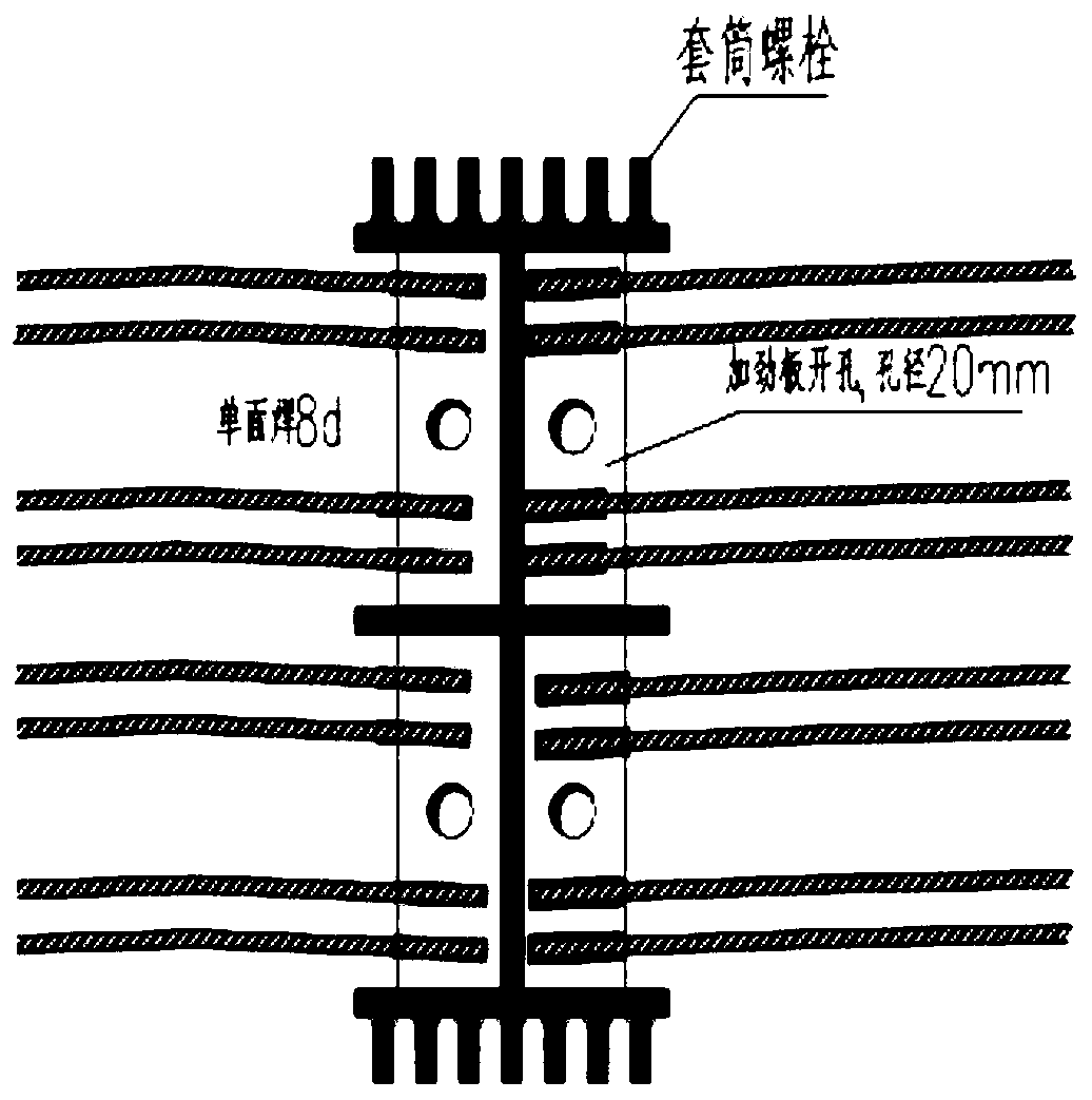
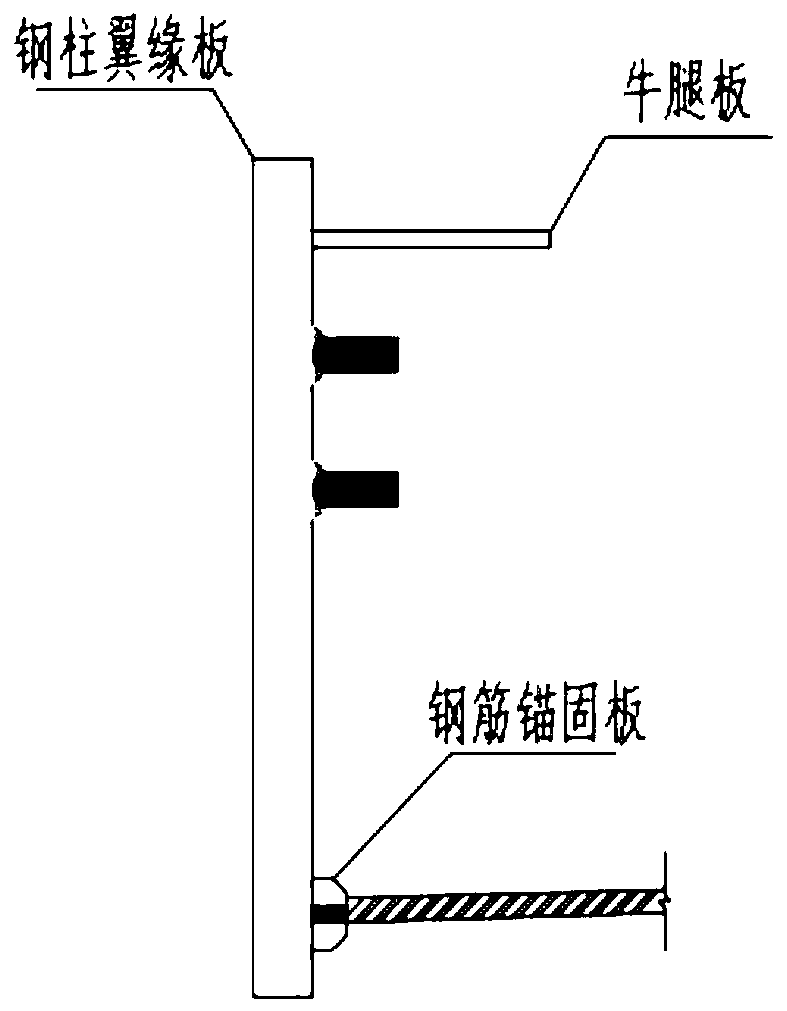
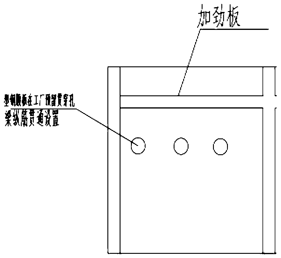
[0034] see Figure 1-5 , the present invention provides a technical solution: a construction method for steel column concrete beam-column joints, comprising the following steps:

[0035] S1: The section size of the shaped steel beam is kept consistent, the position of the gluten is kept through, the bottom reinforcement at the bottom of the gluten meets the flange and the web of the shaped steel, and when the anchorage length of the straight section is satisfied, use a bent anchor or a steel anchorage plate for anchoring;

[0036] S2: Review the design after deepening the drawings provided by the design, and start the construction work after the review is passed and the design is approved;

[0037] S3: When installing the steel frame of the column, first make temporary connections at the upper and lower steel frames, then observe and correct the vertical deviation, and then perform welding or high-strength bolt connection, and then after the steel frame of the beam is installe...

Embodiment 2

[0049] see Figure 1-5 , the present invention provides a technical solution: a construction method for steel-column concrete beam-column joints, comprising the following steps:

[0050] S1: The cross-sectional size of the shaped steel beam is kept consistent, the position of the gluten is kept through, and the bottom reinforcement at the bottom of the gluten meets the flange and web position of the shaped steel. When the anchorage length of the straight section is satisfied, use a bent anchor or a steel anchorage plate for anchoring;

[0051] S2: Review the design after deepening the drawings provided by the design, and start the construction work after the review is passed and the design is approved;

[0052]S3: When installing the steel frame of the column, first make temporary connections at the upper and lower steel frames, then observe and correct the vertical deviation, and then perform welding or high-strength bolt connection, and then after the steel frame of the beam...

Embodiment 3

[0064] see Figure 1-5 , the present invention provides a technical solution: a construction method for steel column concrete beam-column joints, comprising the following steps:

[0065] S1: The section size of the shaped steel beam is kept consistent, the position of the gluten is kept through, the bottom reinforcement at the bottom of the gluten meets the flange and the web of the shaped steel, and when the anchorage length of the straight section is satisfied, use a bent anchor or a steel anchorage plate for anchoring;

[0066] S2: Review the design after deepening the drawings provided by the design, and start the construction work after the review is passed and the design is approved;

[0067] S3: When installing the steel frame of the column, first make temporary connections at the upper and lower steel frames, then observe and correct the vertical deviation, and then perform welding or high-strength bolt connection, and then after the steel frame of the beam is installe...


PUM


Abstract

The invention discloses a construction method of a section steel column concrete beam-column joint. The construction method comprises the following steps: S1, the section sizes of section steel beamskeep consistent; S2, a drawing provided by design is deepened, and then design review is conducted; S3, a section steel skeleton of a column is mounted; S4, the section steel skeleton of the column ismachined; S5, the positions, encountering webs, of face bars are constructed; and S6, the beam-column joint and the lower parts of section steel flanges of the beams are constructed. The positions, encountering the webs, of the face bars, and the positions, encountering the flanges, of the face bars are constructed; the positions, encountering the webs, of the face bars are constructed accordingto the steps: stiffening plate welding, hole forming and penetrating of two/three rows of steel bars, and hole forming in the webs in a factory; the positions, encountering the flanges, of the face bars are constructed according to the steps: bracket welding, and machining of two/three rows of steel bars; bottom bars of the beam-column joint adopt steel bar anchor plates; and because of improvement of the construction method, on-site construction operation can be convenient, input of the construction amount and labor force is lowered, the total construction progress is accelerated, the construction period is shortened, and the construction cost is lowered.

Description

technical field [0001] The invention relates to the technical field of steel-reinforced concrete, in particular to a construction method for steel-column concrete beam-column joints. Background technique [0002] The steel reinforced concrete rigid structure can not only meet the stress requirements of high-rise and long-span structures, but also meet the fire protection requirements of buildings. However, the disadvantages of this type of structure are that the joints between the steel column and the concrete beam are complicated, the construction is difficult, and the construction quality is difficult to guarantee. Therefore, the connection between the steel bar and the steel bar in the rigid structure becomes the most important thing in the construction. [0003] The dense steel bars at the bottom of the beam are not suitable for construction, and the joints of the steel bone columns are deepened. In the actual construction site, there will be structural stress problems d...

Claims


Application Information

Patent Timeline
Patent Type & Authority Applications(China)
IPC IPC(8): E04B1/58
CPCE04B1/58
Inventor 郭志亚孙伟晏立袁成毅程硕
Owner GUANGDONG CONSTAR CONSTR GRP CO LTD
Why Eureka
Try Eureka