Horizontal shaft top mounted pipe cleaning valve

A top-mounted, pigging technology, applied to the valve details, valve device, valve housing structure, etc., can solve the problems of difficulty in receiving the pig, complex structure, heavy weight, etc., to reduce the overall weight, simplify the overall structure, The effect of weight reduction

Pending Publication Date: 2019-09-06
ZIGONG ZIGAO VALVE
View PDF1 Cites 1 Cited by
  • Summary
  • Abstract
  • Description
  • Claims
  • Application Information

AI Technical Summary

Problems solved by technology

However, this patent needs to set up a separate pig receiving and releasing port on the side of the valve body, which not only has the defects that it is very difficult to collect the pig, but also has defects such as complex structure, heavy weight, and high cost.

Method used


Image

  • Horizontal shaft top mounted pipe cleaning valve
  • Horizontal shaft top mounted pipe cleaning valve
  • Horizontal shaft top mounted pipe cleaning valve

Examples


Embodiment 1

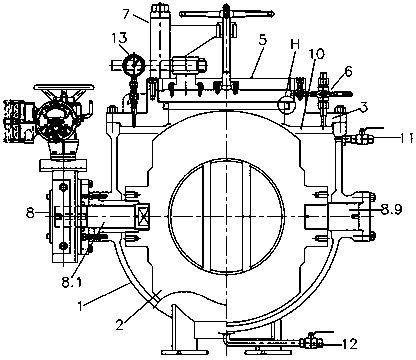
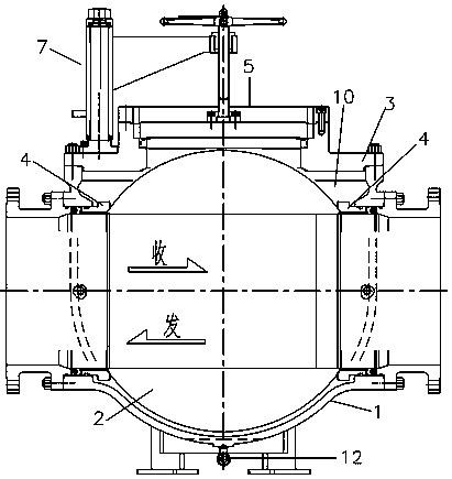
[0044] This embodiment provides a horizontal shaft top-mounted pigging valve, such as figure 1 , 2 As shown, it includes valve body 1, sphere 2, vent valve 11, blowdown valve 12, pressure gauge 13, valve cover 3, valve seat 4, opening and closing sealing mechanism 5, opening and closing interlocking mechanism 6, rotating mechanism 7 and ball control Mechanism 8, the positions and connections of each component are as follows:

[0045] The upper end of the valve body 1 is provided with a loading and unloading port 10. The diameter of the loading and unloading port 10 is slightly larger than the outer diameter of the ball 2. Both the ball 2 and the valve seat 4 are loaded into the valve body 1 through the loading and unloading port 10. The valve seat 4 is provided with a pull rod The hole and the valve seat 4 are symmetrically arranged on the upstream inlet end and the downstream outlet end of the valve body 1 , and the ball 2 is located between the valve seats 4 .

[0046] The...

Embodiment 2

[0069] On the basis of Example 1, the horizontal shaft top-mounted pigging valve also includes a hoisting mechanism 9, and the hoisting mechanism 9 includes a fixed vertical shaft 9.1, a beam 9.2, a reinforcing rib 9.3, a pulling line 9.4, a rotating sleeve 9.5 and Explosion-proof manual hoist 9.6, the lower end of the fixed vertical shaft 9.1 is fixed on the valve cover 3, the rotating sleeve 9.5 is movable sleeved on the upper end of the fixed vertical shaft 9.1, the beam 9.2 is fixed on the rotating sleeve 9.5, and the reinforcing rib 9.3 is fixed on the beam 9.2 and the rotating sleeve 9.5 Between, explosion-proof manual hoist 9.6 is connected on the beam 9.2, and traction line 9.4 is connected on the explosion-proof manual hoist 9.6. The ball 2 and the pig can be quickly hoisted into or out of the valve body 1 through the hoisting mechanism 9 .


PUM


Abstract

The invention discloses a horizontal shaft top mounted pipe cleaning valve. The horizontal shaft top mounted pipe cleaning valve comprises a valve body, a ball body, a valve cover, a valve base, an opening/closing sealing mechanism, an opening/closing interlocking mechanism, a rotating mechanism and a ball body control mechanism; a loading/unloading port is formed in the upper end of the valve body; the ball body and the valve base are mounted in the valve body through the loading/unloading port; the valve cover is fixed on the valve body, and is provided with an opening/closing hole; the opening/closing sealing mechanism is fixed on the valve cover; the opening/closing interlocking mechanism is fixed on the valve cover; the rotating mechanism is fixed on the valve cover; the ball body control mechanism comprises a valve rod and a fixed shaft; and the valve rod is matched with the fixed shaft to control the ball body to rotate. The ball body, a pipe cleaner and a valve inner part all can be mounted in the valve body from the top, so that the top mounting structure is really realized, meanwhile, the structure of the pipe cleaning valve is simplified, the total weight of the pipe cleaning valve is reduced, the overall sealing performance of the pipe cleaning valve is improved, the convenient collecting and releasing operations of pipe cleaners with various sizes and weights is achieved, and meanwhile, the real on-line maintenance function is achieved.

Description

technical field [0001] The invention belongs to the field of special equipment for pipeline transportation, and in particular relates to a horizontal-shaft top-mounted pigging valve. Background technique [0002] The pigging valve is an important equipment for sending or receiving pigs for pipeline cleaning. To ensure efficient and stable pipeline cleaning, it is necessary to strictly follow the standard regulations to ensure that the pigging valve can be loaded or received with a sufficient length of about 1.1 to 1.5 times the diameter of the pig. That is, the effective length of the pigging valve sphere minus the retaining rib is not less than the length of the pig, so the diameter of the pigging valve sphere is large, and the overall shape and size of the pigging valve are also large. Especially for large-diameter pipeline pigging valves, the energy consumption cost of manufacturing materials is very high due to their large size. [0003] The prior art of Chinese patent ...

Claims


Application Information

Patent Timeline
Patent Type & Authority Applications(China)
IPC IPC(8): F16K5/06F16K27/06F16K27/08F16K31/50F16K37/00F16K43/00B66C23/16
CPCF16K5/0636F16K5/0647F16K27/067F16K27/08F16K31/502F16K37/0008F16K37/0091F16K43/001B66C23/163
Inventor 兰正辉顾才利李治舒维泉唐克超文玉龙唐宁杨靖朱超邓旭宏昂仁杰唐琳
Owner ZIGONG ZIGAO VALVE
Why Eureka
Try Eureka