Polarized infrared detector structure

An infrared detector and polarization technology, which is applied in the field of polarized infrared detector structure, can solve the problem of inability to distinguish the detection of polarization directions of infrared rays, and achieve the effects of low cost, better performance and flexible use

Active Publication Date: 2019-09-06
SHANGHAI INTEGRATED CIRCUIT RES & DEV CENT
View PDF4 Cites 5 Cited by
  • Summary
  • Abstract
  • Description
  • Claims
  • Application Information

AI Technical Summary

Problems solved by technology

[0002] Polarized light can assist in image recognition, while traditional infrared detectors mostly use the processing of the incident lens, which cannot detect infrared rays with different polarization directions.

Method used


Image

  • Polarized infrared detector structure
  • Polarized infrared detector structure
  • Polarized infrared detector structure

Examples


Embodiment Construction

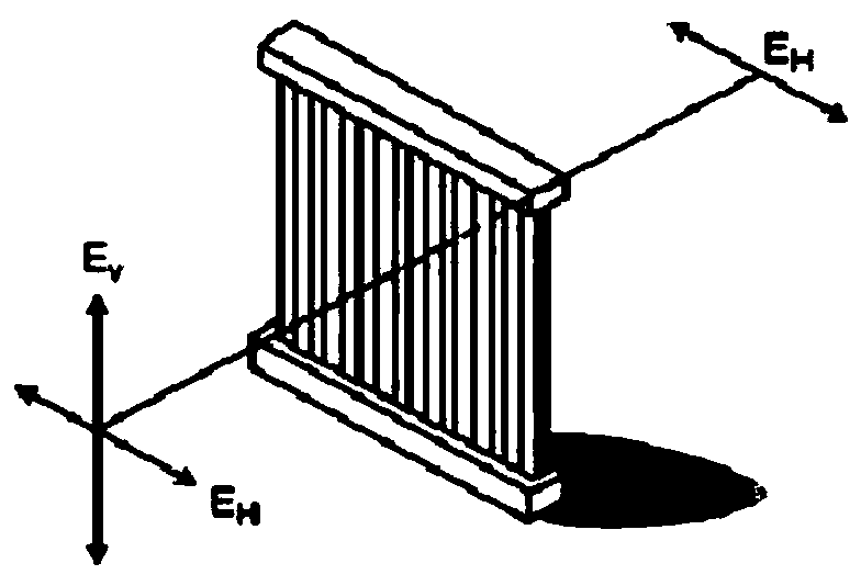
[0025] Please refer to figure 1 , figure 1 Is the schematic diagram of the principle of polarized light incident grating. Such as figure 1 As shown, the polarized light incident on the grating (wires) includes vertically polarized light E V and horizontally polarized light E H (Incident polarized light, vertical (E V ) and horizontal (E H )). Among them, vertically polarized light E V Parallel to the grating direction, horizontally polarized light E H Orthogonal to the grating direction. When polarized light enters the grating, the electric field parallel to the grating dissipates (is attracted) (E fieldparallel to the wires is dissipated), while the electric field perpendicular to the grating passes (E fieldperpendicular to the wires is passed).

[0026] Polarized light can assist in image recognition, and using metal and other materials to form a periodic grating structure can effectively selectively transmit incident polarized light.

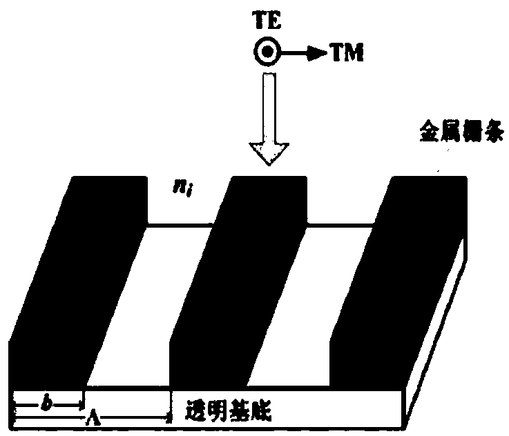
[0027] Please refer to fig...


PUM


Abstract

The invention discloses a polarized infrared detector structure. The polarized infrared detector structure includes a micro-bridge structure and a first metal grating structure stacked on a substrate;the micro-bridge structure is provided with a micro-bridge surface, supports and electrical connection holes; the micro-bridge surface is used for detecting infrared rays; the supports and electricalconnection holes are used for supporting the micro-bridge surface and conducting electrical signals generated by the micro-bridge surface to the substrate; the first metal grating structure is suspended above the micro-bridge surface, including a first metal grating composed of a plurality of first metal grid bars arranged in parallel; and the first metal grating is electrically connected to thesupport at the lower part and the electrical connection hole through a first metal support post. According to the invention, polarized light of a certain direction is selectively transmitted to the micro-bridge surface of the infrared detector; therefore, functions such as graphic recognition can be realized in an auxiliary manner; and the performance is better, the cost is lower, and the use is more flexible.

Description

technical field [0001] The present invention relates to the technical field of infrared detectors, and more particularly relates to a polarized infrared detector structure. Background technique [0002] Polarized light can assist in image recognition, while traditional infrared detectors mostly use the processing of the incident lens, which cannot detect infrared rays with different polarization directions. Contents of the invention [0003] The object of the present invention is to overcome the above-mentioned defects in the prior art and provide a polarized infrared detector structure. [0004] To achieve the above object, the technical scheme of the present invention is as follows: [0005] A polarized infrared detector structure, including a micro-bridge structure and a first metal grating structure stacked on a substrate, the micro-bridge structure is provided with a micro-bridge deck and support and electrical connection holes, the micro-bridge deck For detecting i...

Claims


Application Information

Patent Timeline
Patent Type & Authority Applications(China)
IPC IPC(8): G01J3/02H01L31/0232H01L31/09
CPCG01J3/0224G01J3/0243H01L31/02327H01L31/09
Inventor 康晓旭
Owner SHANGHAI INTEGRATED CIRCUIT RES & DEV CENT
Why Eureka
Try Eureka