Multi-band antenna based on composite left-right hand transmission line

A composite left-handed, multi-band antenna technology, applied in the field of multi-band antennas, compact and miniaturized WiFi antennas, can solve the problems of large size, achieve the effects of gain improvement, compactness, and size reduction

Pending Publication Date: 2019-09-06
HANGZHOU DIANZI UNIV FUYANG ELECTRONIC INFORMATION RES INST CO LTD
View PDF0 Cites 2 Cited by
  • Summary
  • Abstract
  • Description
  • Claims
  • Application Information

AI Technical Summary

Problems solved by technology

[0003] In order to adapt to the rapid development of current broadband connections and meet people's requirements for wireless connection stability and speed, with the current 5GHz WiFi technology, coupled with the original 2.4GHz, the current WiFi dual-band has been formed. According to the international IEEE802.11b / g and IEEE 802.11ac / n protocol standard, the low-frequency working range of WiFi is 2.4-2.4825GHz, and the high-frequency working range is 5.15-5.825GHz. The composite left and right handed transmission line structure antenna, its designed frequency bands are mostly dual frequency bands, which can only cover two of the frequency bands in the present invention or cover one frequency band and other frequency bands in the present invention. It is necessary to study a solution to solve this problem. defect

Method used


Image

  • Multi-band antenna based on composite left-right hand transmission line
  • Multi-band antenna based on composite left-right hand transmission line
  • Multi-band antenna based on composite left-right hand transmission line

Examples


Embodiment Construction

[0027] The technical solutions provided by the present invention will be further described below in conjunction with the accompanying drawings.

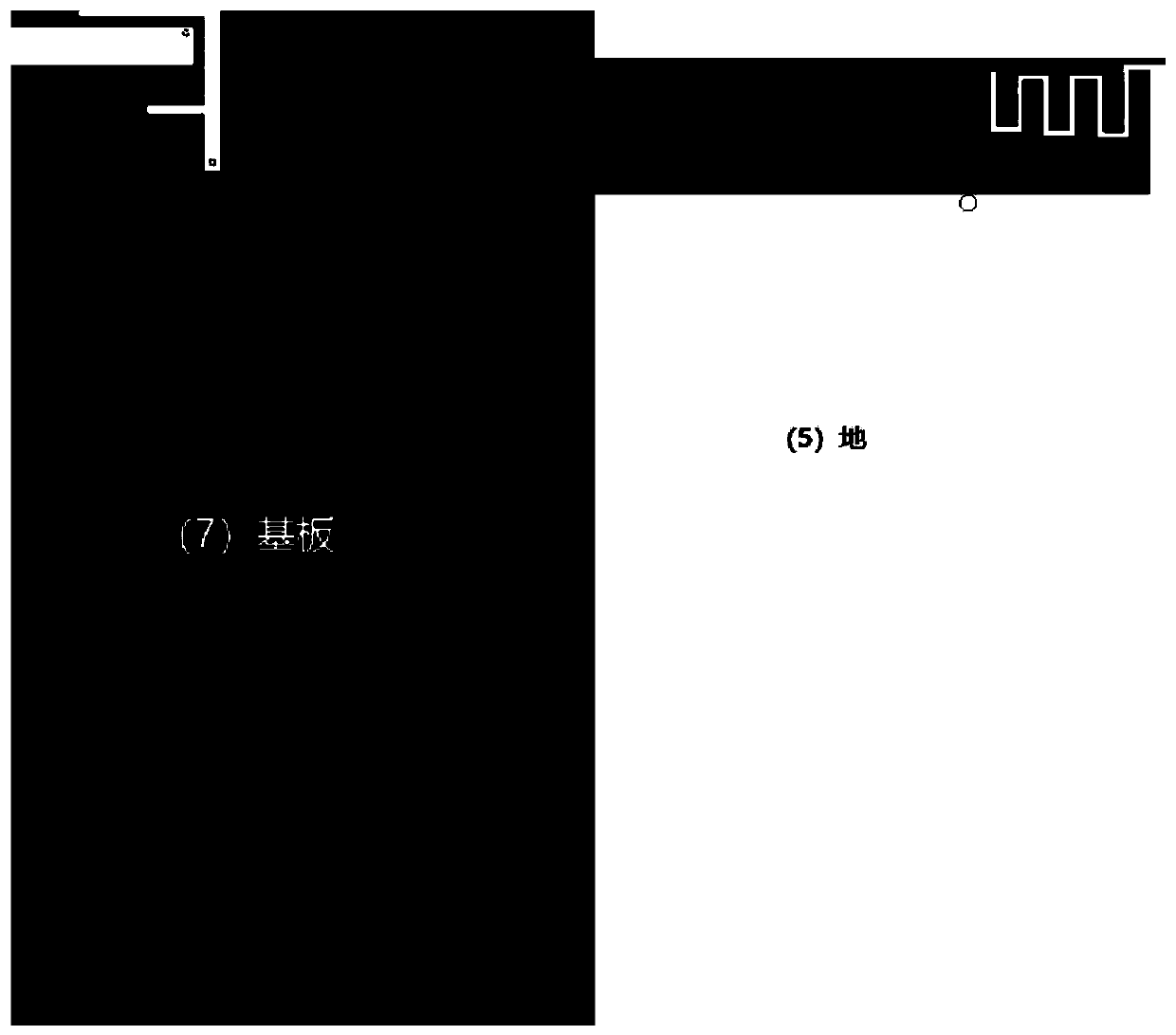
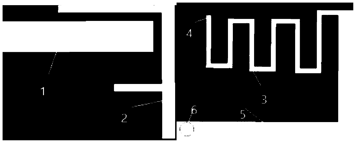
[0028] see Figure 1-2 , which is a structural block diagram of a multi-band antenna based on a composite left-handed transmission line disclosed by the present invention, including a substrate (7) and a first circuit layer and a second circuit layer respectively arranged on both sides of the substrate (7), wherein, The first circuit layer is at least provided with an inverted F antenna (2) and a rectangular radiation patch (1), and the second circuit layer is provided with at least a meander (3) and a ground (5);

[0029] The multi-band antenna is also provided with a coaxial feeder (6), and the coaxial feeder (6) feeds the inverted F antenna (2);

[0030] The rectangular radiation patch (1) is connected to the meander line (3) through the through hole (4), the meander line (3) is connected to the ground (5), and the rectangular ra...


PUM


Abstract

The invention discloses a multi-band antenna based on a composite left-right hand transmission line. The antenna is composed of a coaxial feed line, a rectangular radiation patch, a through hole, an inverted F antenna, a curved streamline, a ground and an FR4 substrate. The rectangular radiate patch, the inverted F antenna and the curved streamline form a composite left-right hand transmission line structure. The composite left-right hand transmission line structure forms a zero-order resonance mode to generate a low frequency band (670-747GHz) to cover LTE band 12 (698-746GHz). The inverted Fantenna and the rectangular patch form a coupling structure to generate a WiFi low frequency band (2.18-2.52 GHz) to cover the 2.4 GHz WiFi band. The inverted F antenna generates the WiFi high frequency band (4.73-6.38 GHz) to cover the 5.0 GHz WiFi band. Due to the existence of the zero-order resonance mode, the antenna size is small enough, the actual volume of the antenna is small enough, integration and processing are easy and the maximum gain in the entire frequency band is 9.17 dB so that the multi-band antenna can be applied to a mobile phone.

Description

technical field [0001] The invention belongs to the technical field of antennas, and specifically relates to a multi-band antenna based on a composite left-handed transmission line, which forms multiple frequency bands based on a CRLH-TL ZOR (composite left-handed material transmission line-zero-order resonance) structure to cover LTEband 12 (698-746GHz) and Compact and miniaturized WiFi antenna for WiFi 2.4GHz and 5.0GHz dual bands. Background technique [0002] In recent years, due to the continuous advancement of the technology era, people's demand for portable mobile communication has increased, and at the same time, there is also the rapid wireless transmission of a large amount of information such as images and videos. The development of wireless communication systems at home and abroad is also getting faster and faster. As a front-end device for transmitting and receiving electromagnetic wave signals, antennas play a very important role in radio systems. At the same ...

Claims


Application Information

Patent Timeline
Patent Type & Authority Applications(China)
IPC IPC(8): H01Q23/00H01Q5/10H01Q5/20H01Q5/307H01Q5/50H01Q1/48H01Q1/50H01Q1/38
CPCH01Q1/38H01Q1/48H01Q1/50H01Q5/10H01Q5/20H01Q5/307H01Q5/50H01Q23/00
Inventor 程知群周伟伟熊英健金江亮
Owner HANGZHOU DIANZI UNIV FUYANG ELECTRONIC INFORMATION RES INST CO LTD
Why Eureka
Try Eureka