DC power supply active protection device for substation based on fault location and protection method thereof

A technology of fault location and DC power supply, which is applied in the direction of emergency protection circuit devices, circuit devices, parts of emergency protection devices, etc. The effect of leapfrog tripping fault, improving continuity and reducing engineering quantity

Pending Publication Date: 2019-09-06
STATE GRID LIAONING ELECTRIC POWER RES INST +4
View PDF0 Cites 3 Cited by
  • Summary
  • Abstract
  • Description
  • Claims
  • Application Information

AI Technical Summary

Problems solved by technology

[0002] For the DC system of the substation, due to various reasons, the DC system in the station often has faults such as grounding and short circuit. The single-point grounding of the DC system in the station is not allowed to run for a long time. A fault will cause a short circuit in the DC system, causing DC power loss
[0003] There are many deficiencies in the existing solutions and fault location techniques for ground faults in DC systems: due to the poor anti-interference ability of the finder, it will cause false alarms for ground faults, and any wires connected to the DC bus must be searched. The large amount of engineering makes it impossible to quickly and accurately locate the ground fault; in addition, the current DC system basically relies on passive tripping and fusing protection of circuit breakers and fuses, and cannot realize active monitoring and active protection of DC faults

Method used


Image

  • DC power supply active protection device for substation based on fault location and protection method thereof
  • DC power supply active protection device for substation based on fault location and protection method thereof
  • DC power supply active protection device for substation based on fault location and protection method thereof

Examples


Embodiment Construction

[0039] The present invention can be better understood from the following examples. However, those skilled in the art can easily understand that the content described in the embodiments is only for illustrating the present invention, and should not and will not limit the present invention described in the claims.

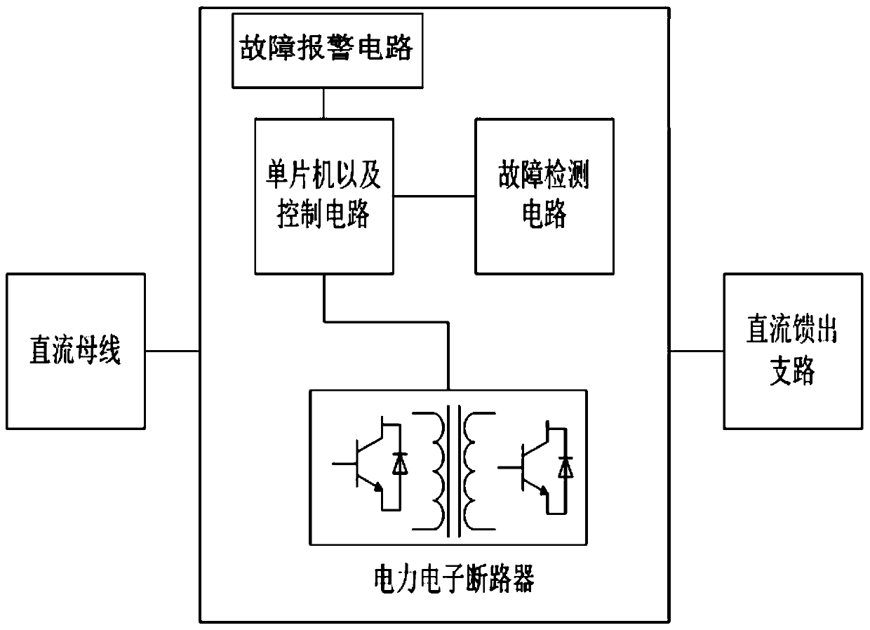
[0040] Such as figure 1As shown, the present invention is based on the fault location DC power active protection device for substations. The protection device is connected in series between the DC power supply and the DC feed-out branch, and the distance between the DC bus (DC power supply) and each DC feed-out branch The protection device of the present invention (each DC feed-out branch circuit is connected in parallel with each other), the input terminal of the protection device of the present invention is connected with the DC bus (DC power supply), and the output terminal of the protection device of the present invention is connected with the DC feed-out branch ...


PUM


Abstract

The invention discloses a DC power supply active protection device for a substation based on fault location. The protection device is arranged between a DC bus and each DC feed-out branch. The protection device comprises a single-chip microcomputer control circuit and a power electronic circuit breaker and a fault detection circuit which are connected with the single-chip microcomputer control circuit. The output end of the DC bus is connected with the input end of the power electronic circuit breaker. The output end of the power electronic circuit breaker is connected with the corresponding DC feed-out branch. The control signal output end of the single-chip microcomputer control circuit is connected with the control signal input end of the power electronic circuit breaker. The fault detection circuit comprises a voltage and current sampling circuit and a grounding fault detection circuit. According to the DC power supply active protection device, the grounding and short circuit faultof the DC system in the substation can be discovered in time, the corresponding fault DC branch can be accurately located and the voltage outputted to the feed-out branch can be timely adjusted according to the fault so that the working continuity, reliability and safety of the DC power supply system of the substation can be improved.

Description

technical field [0001] The invention relates to a DC power active protection device for substations based on fault location, and also relates to a protection method for the DC power active protection device, which belongs to the technical field of electric power automation. Background technique [0002] For the DC system of the substation, due to various reasons, the DC system in the station often has faults such as grounding and short circuit. The single-point grounding of the DC system in the station is not allowed to run for a long time. A fault will cause a short circuit in the DC system, causing DC power loss. [0003] There are many deficiencies in the existing solutions and fault location techniques for ground faults in DC systems: due to the poor anti-interference ability of the finder, it will cause false alarms for ground faults, and any wires connected to the DC bus must be searched. The large amount of engineering makes it impossible to quickly and accurately lo...

Claims


Application Information

Patent Timeline
Patent Type & Authority Applications(China)
IPC IPC(8): H02H7/22H02H7/26H02H1/00
CPCH02H1/0007H02H7/22H02H7/268
Inventor 朱钰张武洋汪洋邹学毅严建海
Owner STATE GRID LIAONING ELECTRIC POWER RES INST
Why Eureka
Try Eureka