Collecting pipe cap

A technology of collecting tubes and caps, which is applied in the field of caps of collecting tubes to achieve the effects of avoiding liquid leakage and ensuring sealing

Active Publication Date: 2019-09-10
ZHONGSHAN HOSPITAL FUDAN UNIV
View PDF23 Cites 1 Cited by
  • Summary
  • Abstract
  • Description
  • Claims
  • Application Information

AI Technical Summary

Problems solved by technology

However, there is no relevant report about a kind of collection tube cap with good sealing performance, convenient installation and plugging, simple structure, strong practicability, and convenient operation and use by medical personnel.

Method used


Image

  • Collecting pipe cap
  • Collecting pipe cap
  • Collecting pipe cap

Examples


Embodiment 1

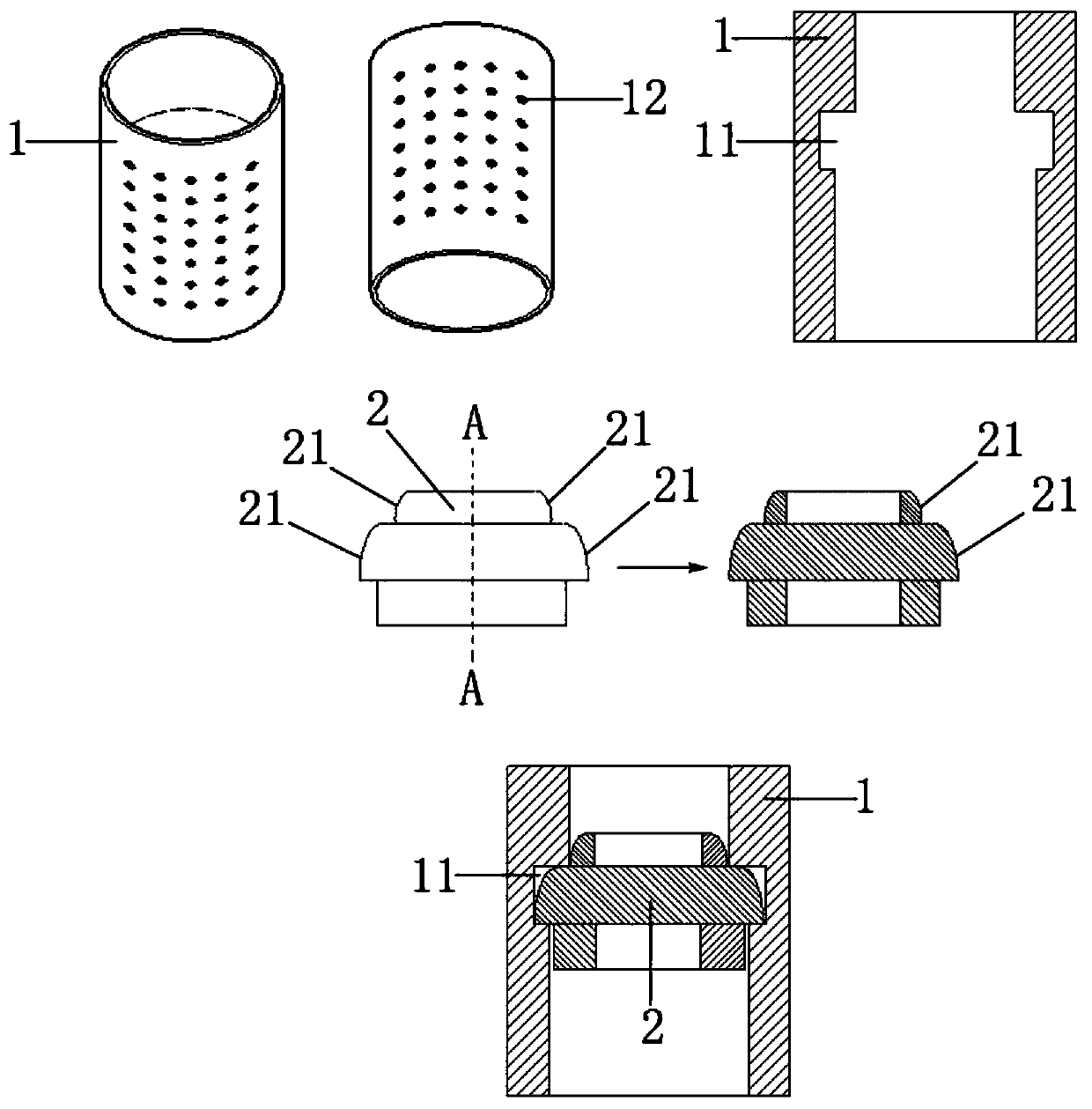
[0051] Please see attached figure 1 , figure 1 It is a schematic diagram of the three-dimensional structure above and below the body of the collection tube cap and the overall plan view, as well as a schematic plan view and A-A cross-sectional diagram of the closing plug of the collection tube cap of the present invention, and a schematic diagram of the assembly of the closing plug and the tube body. A collection tube cover, the collection tube cover includes a tube body 1 and a closure plug 2; the tube body 1 is in a hollow cylindrical structure; a top and a bottom of the tube body 1 are provided for placing the closure The slot 11 for placing the plug 2; the pipe body 1 is provided with an anti-skid structure 12; the diameter of the inner wall at the top of the slot 11 is smaller than the diameter of the inner wall at the bottom; the main body of the plug 2 has a three-layer structure, and the plug 2 The two sides of the upper and middle plug bodies are arc-shaped structure...

Embodiment 2

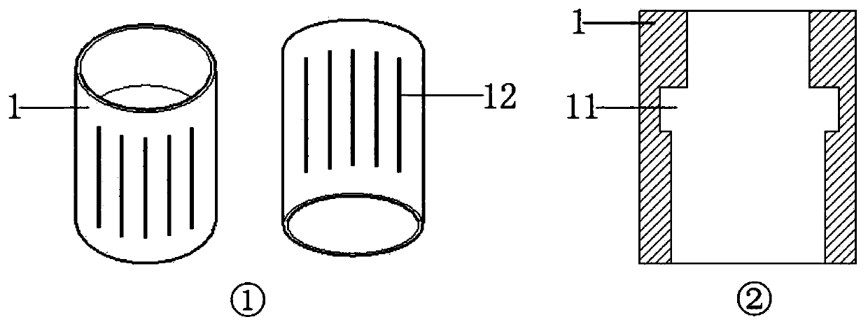
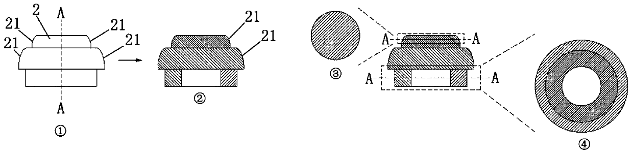
[0055] Please see attached Figure 3A , 3B , 3C, Figure 3A It is a schematic diagram of the three-dimensional structure above and below the tube body of the collection tube cover in Embodiment 2 of the present invention and a schematic diagram of the overall plan. Figure 3B It is an overall schematic plan view of a collection tube cap body in Embodiment 3 of the present invention (wherein, ① is a schematic plan view of a closure plug, ② is a schematic cross-sectional view of a dotted line A-A of a closure plug, and ③ is a top view of a cross-sectional view of a dotted line A-A of a partial structure of a closure plug , ④ is the dotted line A-A cross-sectional top view of the local structure of the closure plug), Figure 3C It is a schematic plan view of the connection between a collection tube cap and a collection tube in Embodiment 2 of the present invention. This embodiment is basically the same as Embodiment 1, the difference is that the connection between the pipe bod...

Embodiment 3

[0057] Please see Figure 4A , 4B , 4C, 4D, Figure 4A It is a schematic diagram of the three-dimensional structure above and below the tube body of the collection tube cap of Embodiment 3 of the present invention and a schematic diagram of the overall plan. Figure 4B It is the overall and partial schematic diagram of a collection pipe cap body in Embodiment 3 of the present invention (wherein, ① is the overall plan view of the pipe body; ② is the dotted line AA cross-sectional perspective view of the local structure of the pipe body; ③ is the dotted line of the local structure of the pipe body AA section bottom view; ④ is the dotted line AA section top view of the local structure of the pipe body), Figure 4C It is a schematic plan view of the bottom of the collection tube cover and the nozzle of the collection tube in Embodiment 3 of the present invention (wherein, ① is a top view of the bottom structure of the tube body; ② is a top view of the connection structure of the...


PUM


Abstract

The invention relates to a collecting pipe cap. The collecting pipe cap comprises a pipe body and a sealing plug. The pipe body is of a hollow cylindrical structure. A holding clamping groove used foraccommodating the sealing plug is arranged between the top and bottom of the pipe body. The diameter of the top inner wall of the holding clamping groove is smaller than that of the bottom inner wallof the holding clamping groove. A sealing plug body is of a three-layered structure. The diameter of an upper layer plug body is smaller than that of a lower layer plug body, and the diameters of theupper layer plug body and the lower layer plug body are smaller than that of a middle layer plug body, so that a left-right double ring structure is formed; in addition, the two sides of the upper layer plug body and the middle layer plug body of the sealing plug are provided with arc-shaped structures correspondingly; and the holding clamping groove is matched with the middle layer plug body ofthe sealing plug in size and shape. The collecting pipe cap has the advantages that the airtightness is good, mounting, pulling and plugging are convenient, in addition, the structure is simple, the practicability is high, and operation and using are convenient.

Description

technical field [0001] The invention relates to the technical field of cap closing plugs, in particular to a collecting tube cap. Background technique [0002] The medical sealing cork has a certain shape and size of the sealing elastomer product, which is used for sealing the mouth of medical bottle-shaped containers such as glass and plastic. Its structure can be roughly divided into three types: conical, T-shaped and flanged; according to the application, it can be divided into antibiotic bottle stoppers, biological drug bottle stoppers, spray drug bottle stoppers, and infusion bottle stoppers. The rubber material of the bottle stopper must not contain harmful soluble substances such as lead, mercury, arsenic, barium, etc., and has no effect on the medicine that can be loaded, and the bottle stopper itself must not have ejection. Generally, it is made of rubber materials such as NR, IIR and SBR, and is produced by molding, and is widely used in the pharmaceutical and med...

Claims


Application Information

Patent Timeline
Patent Type & Authority Applications(China)
IPC IPC(8): B65D39/00A61J1/14A61J1/05
CPCB65D39/0052A61J1/1412A61J1/05
Inventor 盛磊李雪宁
Owner ZHONGSHAN HOSPITAL FUDAN UNIV
Why Eureka
Try Eureka