Direct-drive barrier gate

A kind of gate machine, direct-drive technology, applied in the field of gates, can solve the problems that the reducer can not be used normally, affect the scope of application of the gate, and the service life of the reducer is short, so as to improve the use range, avoid shaking and unstable, The effect of prolonging the service life

Pending Publication Date: 2019-09-10
东莞市铭诚机电有限公司
View PDF3 Cites 3 Cited by
  • Summary
  • Abstract
  • Description
  • Claims
  • Application Information

AI Technical Summary

Problems solved by technology

[0004] According to the currently published patent documents, in the field of barrier gates, the core of the barrier gate uses a motor with a reducer as the driving source of the barrier, and the motor is generally an AC asynchronous motor with a worm gear reducer or a gear reducer as a power control gate. Rod lifting, this configuration has the following disadvantages: 1. The structure of the gate movement is complex and the volume is large; 2. The power of the single-phase asynchronous motor is only 30-40% inefficient after being output through the worm gear reducer. Due to the single-phase asynchronous The speed of the motor is high, and the input shaft directly connected to the motor in the reducer also has a high speed. The input shaft is installed on the reducer housing through bearings, which makes the bearings easy to wear, which in turn causes the brake lever to vibrate Instability and the phenomenon that the brake lever does not stop in place, there are huge hidden dangers of performance and failure. In this way, the bearing on the reducer housing needs to be replaced, which makes the service life of the reducer shorter; 3. The use of the reducer needs Add lubricating oil, so that there will be oil leakage during the use of the reducer, and the lubricating oil has a freezing point. For example, in the winter environment in the north, the outdoor temperature is more than ten degrees below zero. The lubricating oil will be frozen, resulting in the abnormal use of the reducer and affecting the scope of application of the barrier gate

Method used


Image

  • Direct-drive barrier gate
  • Direct-drive barrier gate
  • Direct-drive barrier gate

Examples


Embodiment Construction

[0022] The following are specific embodiments of the present invention and in conjunction with the accompanying drawings, the technical solutions of the present invention are further described, but the present invention is not limited to these embodiments.

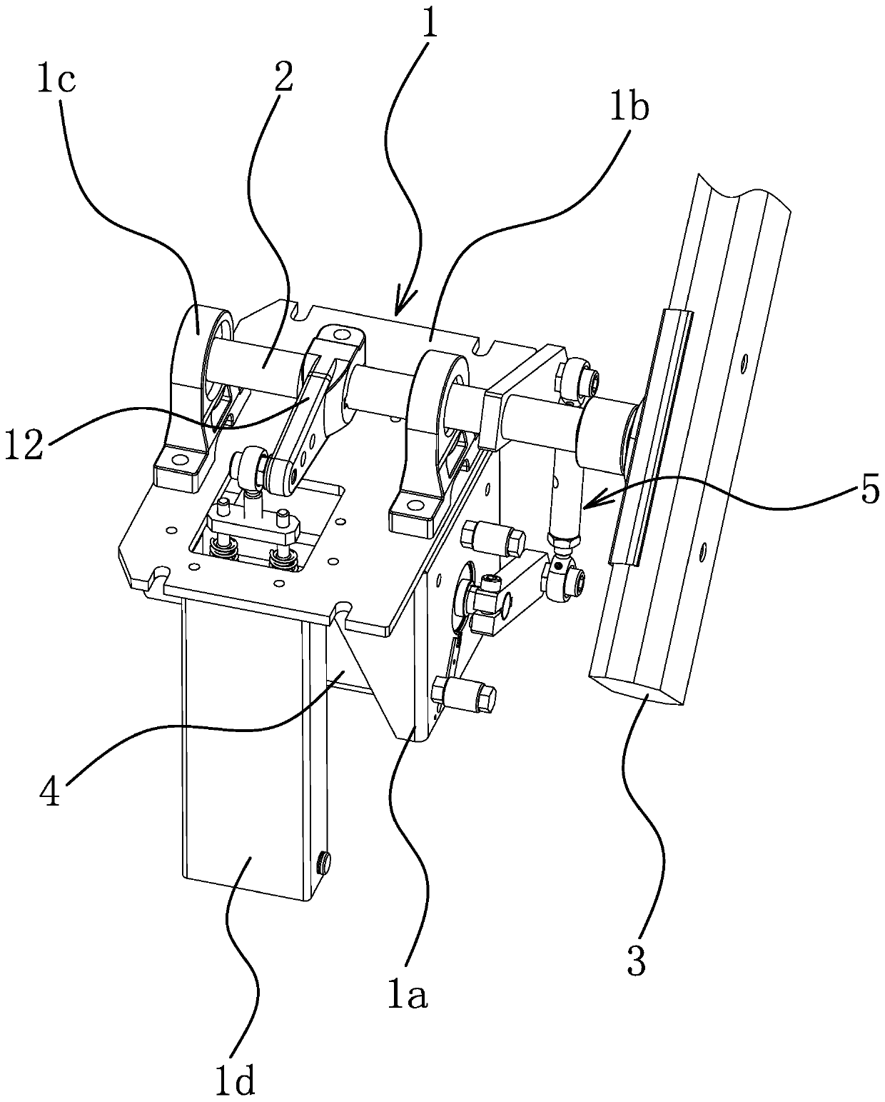
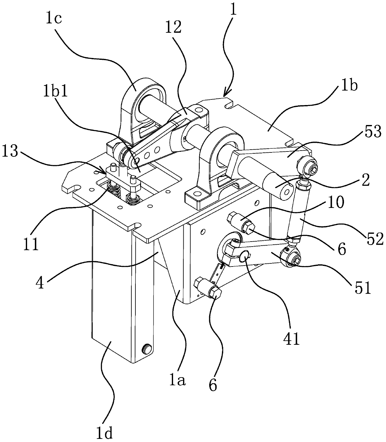
[0023] Such as figure 1 with figure 2 As shown, the direct-drive barrier gate includes a base 1, and the base 1 includes a backing plate 1b, two bearing housings 1c fixed on the upper surface of the backing plate 1b, a fixed plate 1a fixed on the lower surface of the backing plate 1b, and a fixing frame 1d, the output shaft 2 is rotatably connected to the bearing seat 1c, the gate lever 3 is fixed at one end of the output shaft 2, and the motor 4 is fixed on the fixed plate 1a.

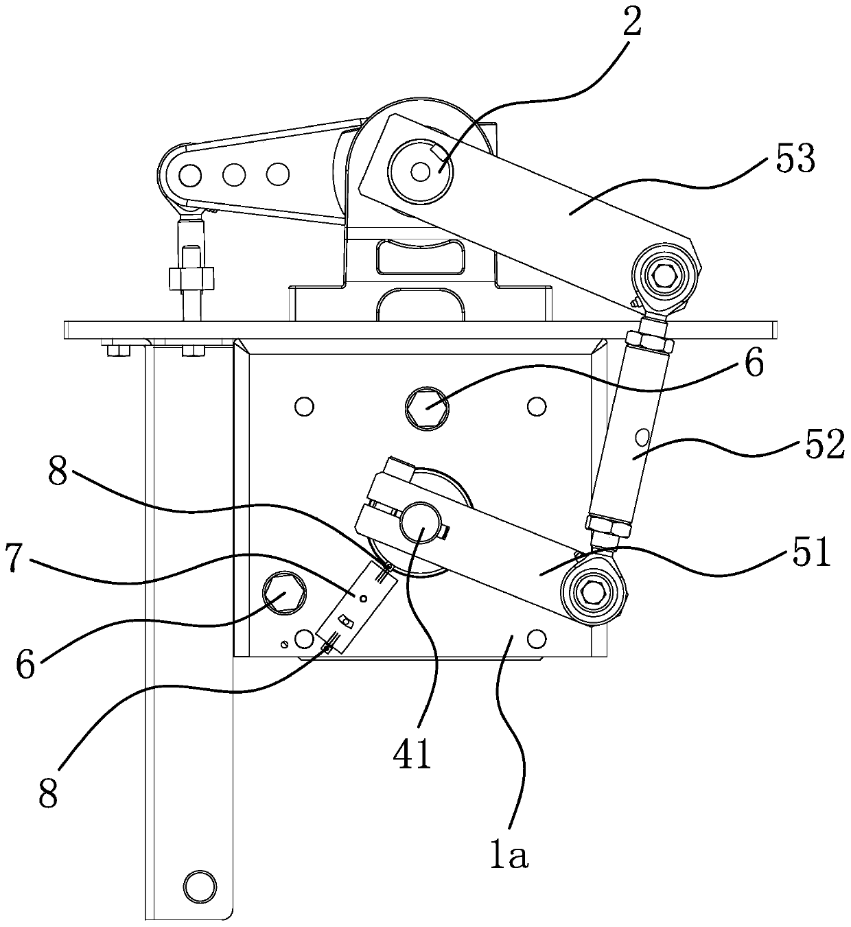
[0024]Further, the motor 4 is a low-speed high-torque permanent magnet synchronous motor, and the motor 4 drives the output shaft 2 to rotate through the link mechanism 5. The link mechanism 5 includes a connecting rod one 51, a connecting rod t...


PUM


Abstract

The invention provides a direct-drive barrier gate and belongs to the technical field of barrier gates. The problem of short service life of an existing barrier gate is solved. The direct-drive barrier gate comprises a base, an output shaft, a barrier gate rod and a motor, wherein the output shaft is rotationally arranged on the base, the barrier gate rod is fixed at one end of the output shaft, and the motor is fixed on the base; the motor is a low-speed large torque permanent magnet synchronous motor; and the motor drives the output shaft to rotate through a connecting rod mechanism. According to the direct-drive barrier gate, the power output efficiency is enhanced, the service life of the barrier gate is prolonged, problems that the shaking of the barrier gate rod is unstable and the barrier gate rod is not stopped in place after long-time use of the barrier gate rod are solved, the position accuracy during swinging of the barrier gate rod is improved, the locating of the barrier gate rod is more stable and accurate, the potential safety hazards and fault risks of the barrier gate are obviously reduced, the use range of the barrier gate is enlarged, the service life of a barrier gate core is prolonged by 3-5 times in the case of guaranteeing that the manufacturing cost is slightly increased (by 20-30%), the cost performance of the barrier gate core is improved, and broad market prospect is realized.

Description

technical field [0001] The invention belongs to the technical field of barrier gates, in particular to a direct-drive barrier gate machine. Background technique [0002] Barrier gate, also known as car stopper, is a channel entrance and exit management device specially used to restrict motor vehicles on the road. It is now widely used in highway toll stations and parking lot systems to manage vehicle passages, and is used to manage the entry and exit of vehicles. The barrier gate core is An important component of the barrier, which provides power for the entire barrier. [0003] At present, China Patent Network discloses a barrier gate mechanism [authorized announcement number: CN204039946U], which includes a motor and a reducer. The reducer includes a box. The box is equipped with a primary worm, a secondary worm, a primary The first-stage worm gear and the power output shaft, one end of the first-stage worm is connected to the motor shaft, and the other end extends into t...

Claims


Application Information

Patent Timeline
Patent Type & Authority Applications(China)
IPC IPC(8): E01F13/06
CPCE01F13/06
Inventor 罗小华
Owner 东莞市铭诚机电有限公司
Why Eureka
Try Eureka