Flexible DC energy dissipation apparatus and circulating current control method thereof

An energy-consuming device and flexible DC technology, applied in the direction of output power conversion device, AC power input conversion to DC power output, power transmission AC network, etc., can solve the problem of limited platform space and load, difficult device installation, and complex circuit structure and other issues, to achieve the effects of reducing land and space, easy installation, and simplifying the overall circuit structure

Active Publication Date: 2019-09-10
ELECTRIC POWER RESEARCH INSTITUTE, CHINA SOUTHERN POWER GRID CO LTD +1
View PDF5 Cites 7 Cited by
  • Summary
  • Abstract
  • Description
  • Claims
  • Application Information

AI Technical Summary

Problems solved by technology

However, this technical solution is suitable for land island power generation systems, but for offshore wind farms, the converter station on the side of the wind farm is located on an offshore platform, and the space and load of the platform are limited, making it difficult to install the device
[0006] To sum up, the energy consumption devices in the prior art have the problems of complicated circuit structure, high system cost and difficult installation

Method used


Image

  • Flexible DC energy dissipation apparatus and circulating current control method thereof
  • Flexible DC energy dissipation apparatus and circulating current control method thereof
  • Flexible DC energy dissipation apparatus and circulating current control method thereof

Examples


Embodiment Construction

[0050] The following will clearly and completely describe the technical solutions in the embodiments of the present invention with reference to the accompanying drawings in the embodiments of the present invention. Obviously, the described embodiments are only some, not all, embodiments of the present invention. Based on the embodiments of the present invention, all other embodiments obtained by persons of ordinary skill in the art without creative efforts fall within the protection scope of the present invention.

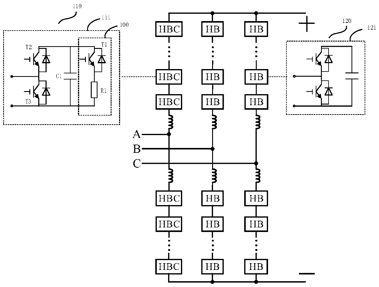
[0051] see figure 1 , is a schematic structural diagram of a flexible DC energy consumption device provided by an embodiment of the present invention, including:

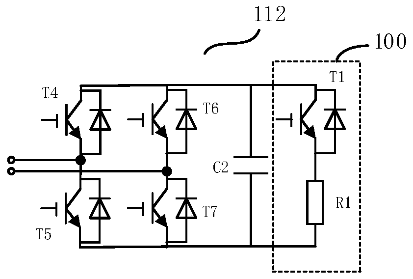
[0052] The hybrid modular multilevel converter includes three-phase units, each unit is divided into an upper bridge arm and a lower bridge arm, and each bridge arm is composed of at least one sub-module in series; wherein, the sub-module includes the first a submodule and a second submodule;

[0053] ...


PUM


Abstract

The invention discloses a flexible DC energy dissipation apparatus and a circulating current control method thereof. The flexible DC energy dissipation apparatus comprises a hybrid modular multi-levelconverter. The hybrid modular multi-level converter includes three phase units, each unit consists of an upper bridge arm and a lower bridge arm, and each bridge arm is composed of at least one sub-module connected in series. The sub-modules of one phase unit are first sub-modules, and the sub-modules of the other two phase units are second sub-modules. The first sub-modules are half-bridge sub-modules with chopper circuits or full-bridge sub-modules with chopper circuits, and the second sub-modules are half-bridge sub-modules or full-bridge sub-modules. When the sub-modules of one phase unitare half-bridge sub-modules with chopper circuits, the sub-modules of the other two phase units are half-bridge sub-modules. When the sub-modules of one phase unit are full-bridge sub-modules with chopper circuits, the sub-modules of the other two phase units are full-bridge sub-modules. The circuit structure can be simplified, and the number of circuit devices can be reduced. Therefore, the system cost is reduced, and the installation is easy.

Description

technical field [0001] The invention relates to the technical field of energy consumption devices, in particular to a flexible DC energy consumption device and a method for controlling its circulation. Background technique [0002] When the flexible DC transmission is applied to connect the island power generation system (such as wind farm) and the AC grid, when the AC grid fails, because the electric energy cannot be sent out, if the power generation system is not cut off, the flexible DC transmission system will fail. In order to enable the flexible DC transmission system to quickly recover after a short-term fault in the grid, it is necessary to install energy-consuming devices to consume excess power during the grid, and to achieve fault ride-through without disconnecting the power generation system. At present, there are various implementation schemes for energy consumption devices: [0003] (1) Install a DC chopper circuit in the DC line. The DC chopper circuit is com...

Claims


Application Information

Patent Timeline
Patent Type & Authority Applications(China)
IPC IPC(8): H02J3/36H02M7/00
CPCH02J3/36H02M7/00Y02E60/60
Inventor 常怡然
Owner ELECTRIC POWER RESEARCH INSTITUTE, CHINA SOUTHERN POWER GRID CO LTD
Why Eureka
Try Eureka