Method and system for correcting magnetic pole position of motor rotor based on incremental encoder, and medium

An incremental encoder, magnetic pole position technology, applied in the field of mechanical control, can solve problems such as the increase of position deviation and the ineffective execution of motor control logic.

Active Publication Date: 2019-09-10
SHENZHEN HPMONT TECH
View PDF2 Cites 13 Cited by
  • Summary
  • Abstract
  • Description
  • Claims
  • Application Information

AI Technical Summary

Problems solved by technology

[0006] The technical problem mainly solved by the present invention is that there is a deviation between the rotor magnetic pole position detected by the encoder and the actual rotor magnetic pole position, and the position deviation will gradually increase with the increase of time, and then the normal control logic of the motor cannot be effectively executed

Method used


Image

  • Method and system for correcting magnetic pole position of motor rotor based on incremental encoder, and medium
  • Method and system for correcting magnetic pole position of motor rotor based on incremental encoder, and medium
  • Method and system for correcting magnetic pole position of motor rotor based on incremental encoder, and medium

Examples


Embodiment 1

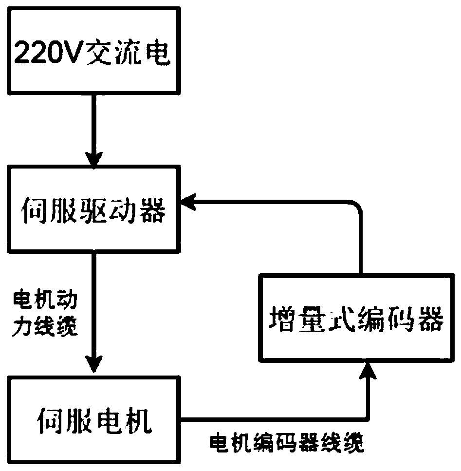
[0065] see figure 1 , Servo driver, composed of a driver board and a control board, controls the start and stop, speed, position, etc. of the servo motor, and performs various protections on the motor, such as overload, overvoltage, overcurrent, etc. It performs the following based on the incremental encoder Method for correcting motor rotor pole position. The servo motor, as a controlled object, can also be called the actuator of the servo drive. The incremental encoder converts the displacement of the motor rotor into a periodic electrical signal, and then converts this electrical signal into a counting pulse, which can calculate the rotor speed, angle, etc. through the number of pulses.

[0066] The embodiment of the present invention provides a method for correcting the magnetic pole position of the motor rotor based on an incremental encoder. The servo driver performs the correction of the magnetic pole position of the motor rotor based on an incremental encoder, or the ...

Embodiment 2

[0128] see Figure 14 In one embodiment, a system for correcting the magnetic pole position of the motor rotor based on an incremental encoder is provided, including a correction given value acquisition unit 61, a current count value acquisition unit 62, a compensation unit 63, a next moment count value acquisition unit 64 and Position determination unit 65 .

[0129] The correction given value acquisition unit 61 is used to acquire the correction given value.

[0130] The current count value acquisition unit 62 is used to obtain the count value of the current moment, wherein, the count value is for the current moment, when the QEP circuit detects the Z pulse signal output of the incremental encoder, the counter is to the incremental encoder The value obtained by counting the output times of the AB pulse signal.

[0131] The compensation unit 63 is configured to obtain a compensation amount according to the correction given value and the count value at the current moment.

...


PUM


Abstract

The invention provides a method and a system for correcting a magnetic pole position of a motor rotor based on an incremental encoder, and a medium. The method comprises the steps of firstly, acquiring a given correction value; then acquiring a counting value at a current moment, wherein the counting value aims at the current moment; when a QEP circuit detects that a Z pulse signal of the incremental encoder is output, counting an output frequency of an AB pulse signal of the incremental encoder by the counter; obtaining a compensation amount according to the given correction value and the counting value at the current moment; according to the compensation amount, calculating a correct counting value at the next moment; and finally outputting the correct magnetic pole position of the motorrotor according to the correct counting value at the next moment. The counting value at the current moment is compared with the given correction value to obtain the compensation amount, and the compensation amount is used for compensating and correcting a position deviation, so that effective execution of normal logic of a motor is ensured.

Description

technical field [0001] The invention relates to the technical field of mechanical control, in particular to a method, system and medium for correcting rotor magnetic pole positions based on an incremental encoder. Background technique [0002] A permanent magnet synchronous motor (referred to as a motor) is a power component that converts electrical energy and mechanical energy. When electrical energy is converted into mechanical energy, the motor exhibits the operating characteristics of a motor, and when electrical energy is converted into mechanical energy, the motor exhibits the operating characteristics of a generator. The motor is mainly composed of components such as rotor, stator winding, speed sensor and casing. Permanent magnet refers to the addition of permanent magnets when manufacturing the motor rotor, so that the performance of the motor can be further improved. The so-called synchronization means that the speed of the rotor is always consistent with the cur...

Claims


Application Information

Patent Timeline
Patent Type & Authority Applications(China)
IPC IPC(8): H02P21/18
CPCH02P21/18H02P2203/03
Inventor 刘启林袁飞平张宁
Owner SHENZHEN HPMONT TECH
Why Eureka
Try Eureka