
Multi-gap vacuum switch based on plasma jet triggering
A vacuum switch and plasma technology, applied in the direction of plasma, spark gap, spark gap components, etc., can solve the problems of limited injection height, poor trigger conduction reliability, narrow working range, etc., to improve injection height and speed, The effect of increased repetition rate and high voltage level
- Summary
- Abstract
- Description
- Claims
- Application Information
AI Technical Summary
Problems solved by technology
Method used
Image

Examples
Embodiment Construction
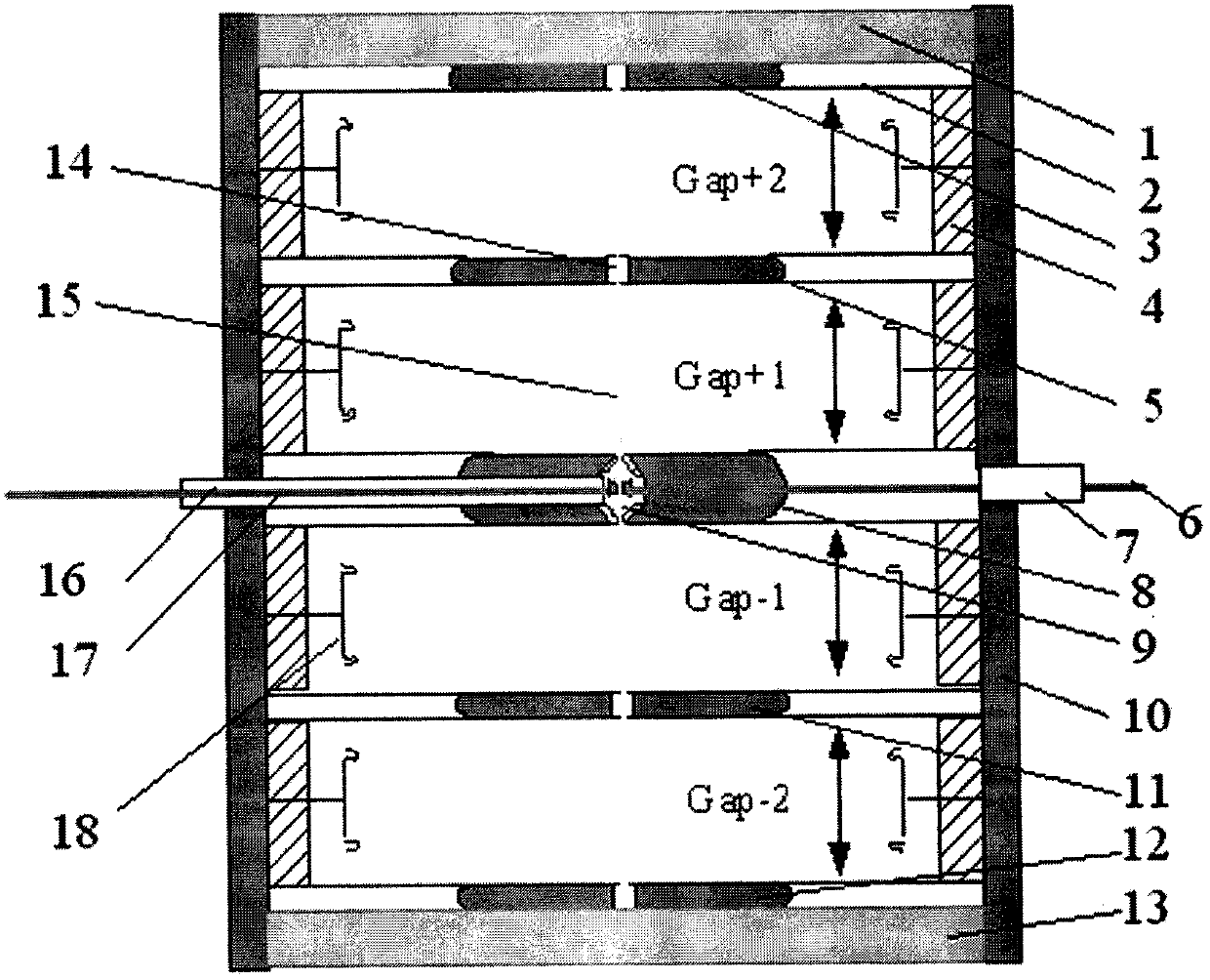
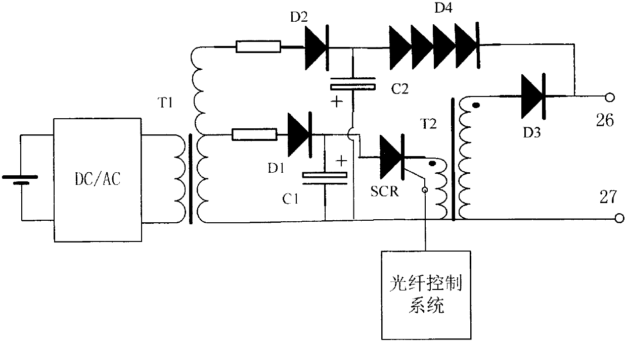
[0015] The multi-gap vacuum switch based on plasma jet trigger mainly consists of a plurality of electrodes 3 with central openings, a middle trigger electrode 8, an annular pressure equalizing ceramic capacitor 4, a shielding cover 18, an insulating sleeve 10, upper and lower connecting end caps 1, 13 and High-voltage pulse trigger and freewheeling circuit (such as image 3 )constitute.
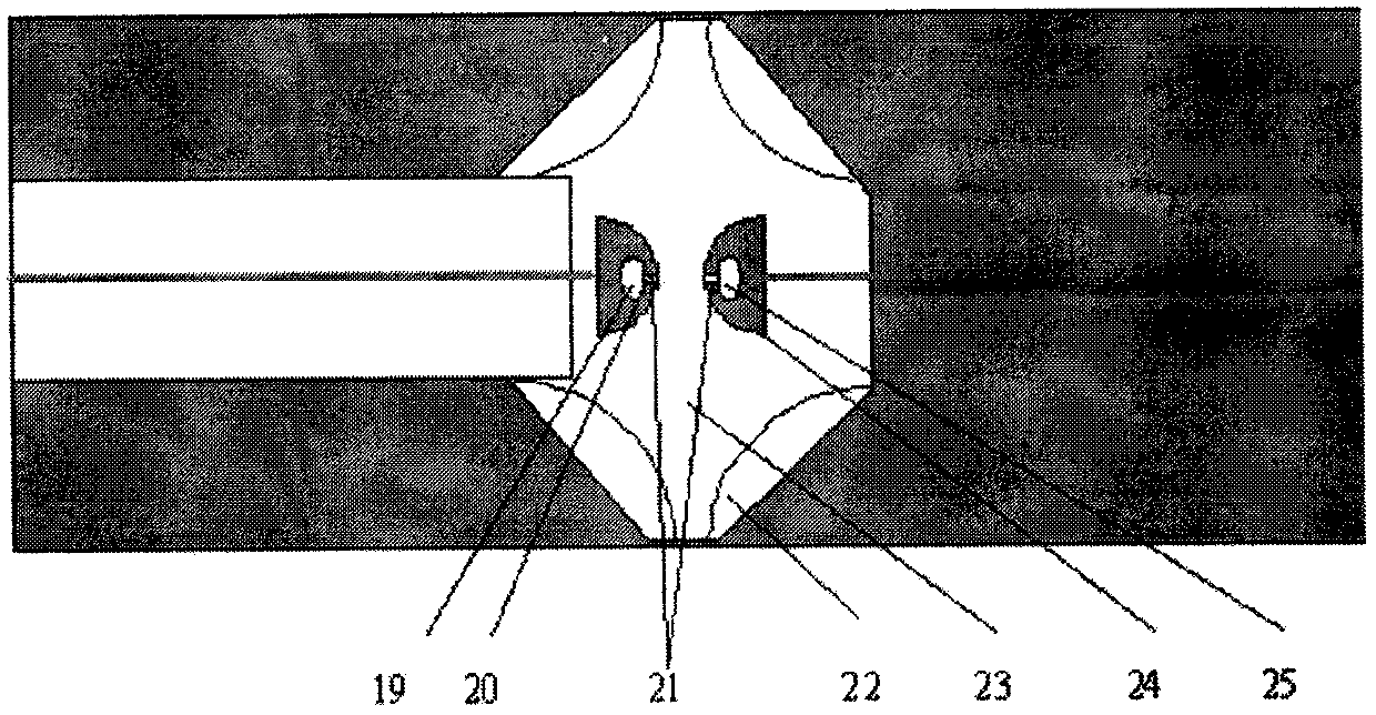
[0016] The switch body of the present invention is as figure 1 As shown, the electrodes 3, 5, 11 and 12 with openings in the center and the middle trigger electrode 8 form four series vacuum gaps. Each gap is composed of a shielding case 18, an annular voltage equalizing ceramic capacitor 4, an insulating support 2 and a central opening electrode. On the outside of the switch body, the insulating sleeve 10 and the upper and lower ports 1, 13 are used to realize the vacuum sealing of the whole switch body, and the vacuum degree is maintained at 10 -5 Below Pa. The whole working process of...
PUM
 Abstract
Description
Claims
Application Information