Heat sink
一种散热器、散热翅片的技术,应用在散热片、间接换热器、传热改性等方向,能够解决冷却水循环能量消耗等问题,达到抑制合计压力损失的效果
- Summary
- Abstract
- Description
- Claims
- Application Information
AI Technical Summary
Problems solved by technology
Method used
Image
Examples
Embodiment approach 1
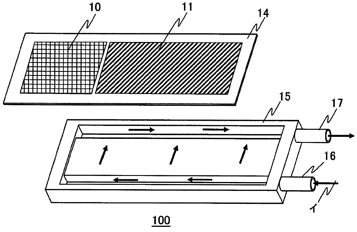
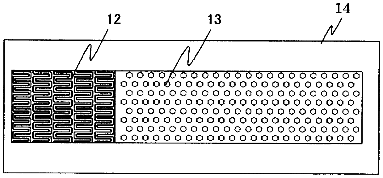
[0028] figure 1 is an exploded perspective view showing the heat sink according to Embodiment 1 of the present invention, figure 2 This is a plan view of the substrate viewed from the surface on which the fins are arranged.
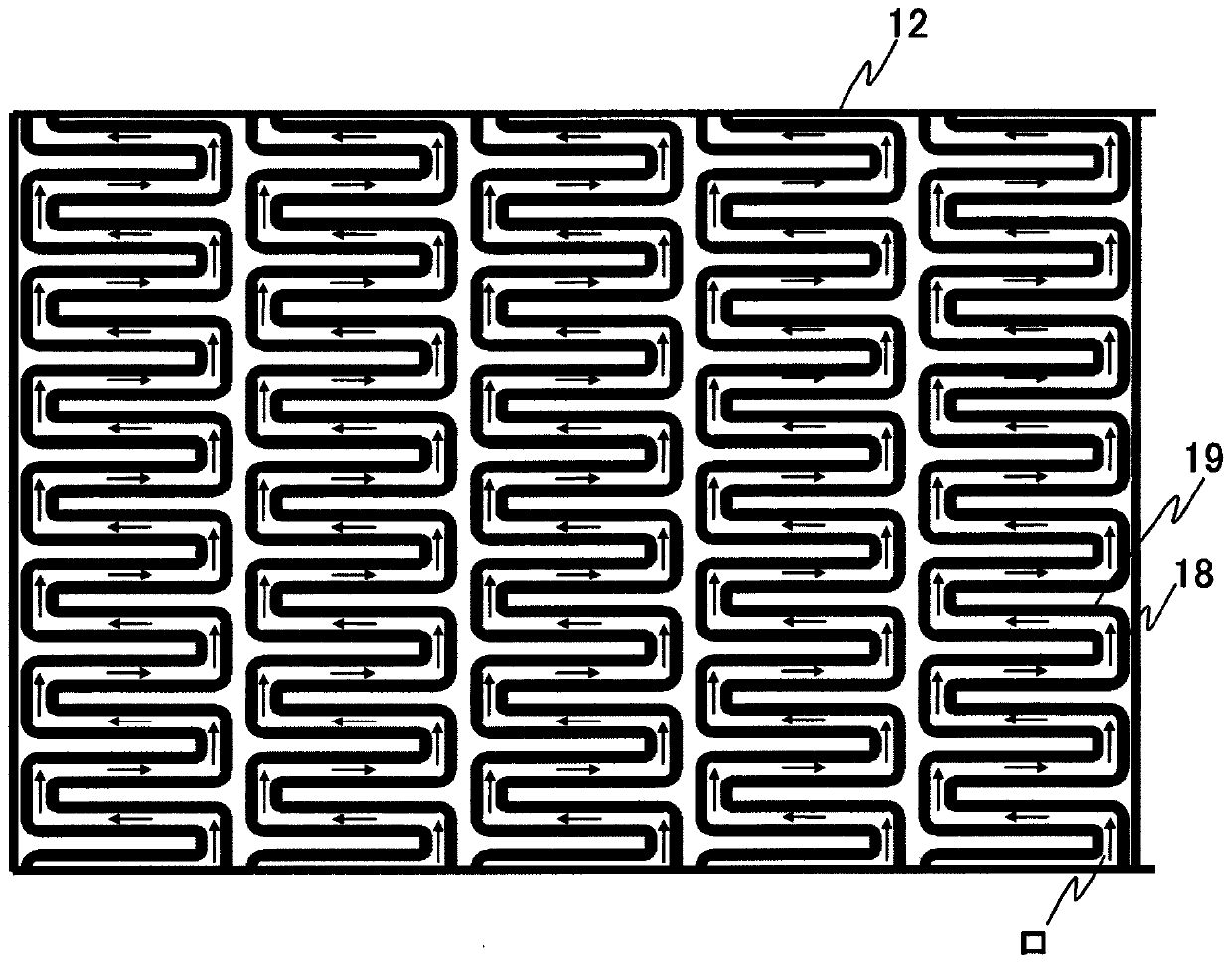
[0029] figure 1 and figure 2 Among them, the heat sink 100 according to Embodiment 1 is configured to include: a surface 10 provided with a heating element having a relatively low heat generation density; a surface 11 provided with a heating element having a relatively high heat generation density; The substrate 14 of the first heat dissipation fins 12 on the back of the surface 10 of the heating element and the needle-shaped second heat dissipation fins 13 provided on the back of the surface 11 with the heating element having a higher heat generation density. The fins 12 have a shape in which a plurality of rows of narrowly spaced zigzag-curved grooves are arranged; a casing 15 that accommodates the substrate 14; 17.
[0030] In the radiator 100, ...
Embodiment approach 2
[0037] Next, a heat sink according to Embodiment 2 of the present invention will be described. Figure 4 It is a schematic diagram of the board viewed from the surface on which the heat dissipation fins of the heat sink 200 according to Embodiment 2 are arranged.
[0038] On the base plate 14, first heat dissipation fins 12 having a large fluid resistance are arranged in the shape of a plurality of rows of zigzag curved grooves, and needle-shaped second heat dissipation fins 13 having a small fluid resistance are arranged in parallel. In other words, a small flow of refrigerant flows through the first heat dissipation fins 12 with larger fluid resistance, and a large flow of refrigerant flows through the second heat dissipation fins 13 with smaller fluid resistance, so the cooling effect of the second heat dissipation fins 13 The performance becomes greater than that of the first heat dissipation fins 12 .
[0039] However, if Figure 4 As shown, if the width W1 of the fin r...
Embodiment approach 3
[0056] Next, a heat sink according to Embodiment 3 of the present invention will be described. Figure 5 It is a perspective view of the case of the heat sink 300 according to the third embodiment, Image 6 means along Figure 5 A cross-sectional view of the A-A line, Figure 7 express Image 6 Enlarged view of part B.
[0057] For example, when the first heat dissipation fins 12 and the needle-shaped second heat dissipation fins 13 in which a plurality of rows of narrowly pitched zigzag grooves are arranged are produced by die casting, forging, or the like, the mold releasability can be improved from the From the viewpoint of mold life, a gap may be provided between the first heat dissipation fin 12 and the second heat dissipation fin 13 .
[0058] However, if a gap is provided between the first heat dissipation fin 12 and the second heat dissipation fin 13, the fluid resistance of the gap becomes extremely small, so that a large amount of refrigerant flows through the ga...
PUM
 Abstract
Description
Claims
Application Information
 - R&D
- Intellectual Property
- Life Sciences
- Materials
- Tech Scout
- Unparalleled Data Quality
- Higher Quality Content
- 60% Fewer Hallucinations
Browse by: Latest US Patents, China's latest patents, Technical Efficacy Thesaurus, Application Domain, Technology Topic, Popular Technical Reports.
© 2025 PatSnap. All rights reserved.Legal|Privacy policy|Modern Slavery Act Transparency Statement|Sitemap|About US| Contact US: help@patsnap.com


