In-vehicle heating machine and method

A technology for vehicles and combustion chambers, which is applied to vehicle components, heating/cooling equipment, air handling equipment, etc., which can solve the problems of inability to balance heating and battery life, avoid freezing problems, stabilize the ambient temperature, and increase the contact area Effect

Pending Publication Date: 2019-09-13
株洲麦格米特电气有限责任公司
View PDF8 Cites 3 Cited by
  • Summary
  • Abstract
  • Description
  • Claims
  • Application Information

AI Technical Summary

Problems solved by technology

[0004] The technical problem to be solved by the present invention is: how to solve the problem that the existing electric vehicles cannot take into account the heating and battery life

Method used


Image

  • In-vehicle heating machine and method
  • In-vehicle heating machine and method
  • In-vehicle heating machine and method

Examples


Embodiment 2

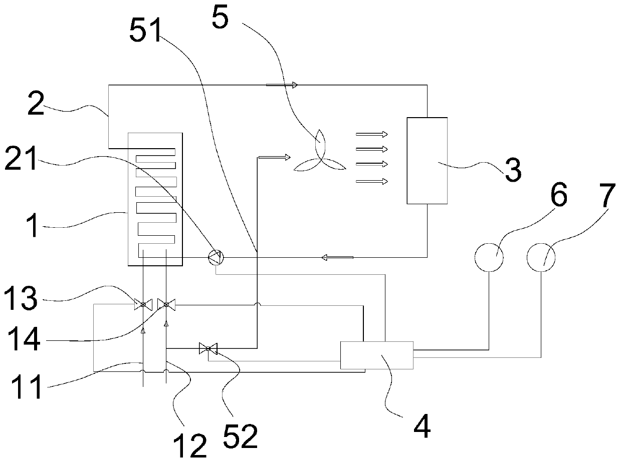
[0046] Such as figure 1 As shown, the second embodiment is based on the first embodiment, and the second embodiment also includes a blower 5 disposed on one side of the heat exchange unit 3 . The heat exchange of the heat exchange unit 3 can be accelerated by increasing the air flow through the blower 5 , the blower 5 is electrically connected to the control unit 3 , and the speed of the blower can be controlled by the control unit 3 .

[0047]Wherein, one side of the blower 5 is provided with a fresh air duct 51, and the fresh air duct 51 is connected to the air duct 11, specifically connected to the front end of the air inlet valve 13, in addition, the air duct may not be connected to the air duct 11, a new pipeline can be reintroduced from the outside of the car body, the freshness of the air in the car can be kept through the fresh air pipeline 51, and the accumulation of harmful gases can be reduced; the fresh air pipeline 51 is provided with a control valve 52, and the c...

Embodiment 3

[0049] Such as figure 1 As shown, on the basis of the first embodiment, the third embodiment further includes a gas sensor 6 , and the gas sensor 6 is electrically connected to the control unit 3 . The gas sensor 6 is mainly a gas sensor for harmful gases, which can detect harmful gases reaching a certain concentration, and feed back to the control unit 3 to open the control valve 52 on the fresh air duct 51 to increase the air flow.

[0050] The third embodiment further includes a temperature sensor 7 , and the temperature sensor 7 is electrically connected to the control unit 3 . The temperature sensor 7 can monitor the temperature in the car in real time, and control the temperature in a suitable range.

[0051] to combine Figure 6 As shown, the air inlet valve 13 and the gas inlet valve 14 are opened by the control unit 3, air and gas are respectively introduced into the air pipeline 11 and the gas pipeline 12, and the circulation pump 21, the heat exchange unit 3, the ...


PUM


Abstract

The invention discloses a vehicle heating machine that comprises a combustion chamber, a circulating heat exchange pipeline, heat exchange units and a control unit; the combustion chamber is providedwith an air pipeline and a gas pipeline; the air pipeline is provided with an air inlet valve, the gas pipeline is provided with a gas inlet valve, the circulating heat exchange pipeline is partiallyarranged in the combustion chamber, two ends of the circulating heat exchange pipeline are connected with heat exchange units respectively, a circulating pump is arranged on the circulating heat exchange pipeline, a heat-carrying agent is arranged in the circulating heat exchange pipeline, and the control unit is electrically connected with the air inlet valve, the gas inlet valve and the circulating pump. The invention further discloses a using method of the vehicle heating machine. The vehicle heating machine has the beneficial effects that the machine is environment-friendly and can accurately adjust the temperature of the environment in the vehicle; the gas inlet valve is controlled by detecting the temperature in the vehicle, so optimal use of combustion heat is guaranteed, and the comfort of the environment in the vehicle is improved.

Description

technical field [0001] The invention relates to the field of automobiles, in particular to an in-vehicle heater and a control method. Background technique [0002] With the continuous increase of electric vehicles, the mileage problem caused by the battery capacity causes the user's actual experience to decline. At the same time, in the cold season, the ambient temperature drops and the battery capacity decreases. Battery life will be even worse. [0003] The information disclosed in this Background section is only for enhancing the understanding of the general background of the present invention and should not be taken as an acknowledgment or any form of suggestion that the information constitutes the prior art that is already known to those skilled in the art. Contents of the invention [0004] The technical problem to be solved by the present invention is: how to solve the problem that the existing electric vehicle cannot take into account the heating and battery life....

Claims


Application Information

Patent Timeline
Patent Type & Authority Applications(China)
IPC IPC(8): B60H1/22
CPCB60H1/2209B60H2001/2271Y02T10/88
Inventor 杨超马赞
Owner 株洲麦格米特电气有限责任公司
Why Eureka
Try Eureka