High-cooling bus duct and preparation method thereof

A busway, high heat dissipation technology, applied in cooling busbar devices, fully enclosed busbar devices, etc., can solve the problems affecting the normal use of busbars, high temperature can not be discharged, casualties and property, etc., to improve the protection effect, improve impact resistance performance, The effect of improving the heat dissipation effect

Inactive Publication Date: 2019-09-13
辰亮科技信息服务(江苏)有限公司
View PDF0 Cites 2 Cited by
  • Summary
  • Abstract
  • Description
  • Claims
  • Application Information

AI Technical Summary

Problems solved by technology

[0003] Due to the compact structure of the busbar and the fact that the busbar will generate a lot of heat after working for a long time, the existing busway generally has a high sealing performance and poor heat dissipation performance, and the high temperature cannot be discharged, resulting in a relatively high working temperature for the busbar and the busway In this case, it will not only affect the normal use of the busbar, but also may cause the busbar to burn, resulting in casualties and property losses.

Method used


Image

  • High-cooling bus duct and preparation method thereof
  • High-cooling bus duct and preparation method thereof
  • High-cooling bus duct and preparation method thereof

Examples


Embodiment 1

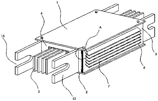
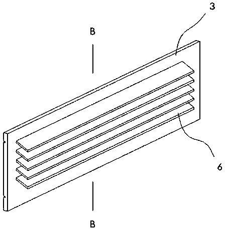
[0033] This embodiment provides a high heat dissipation busway, including an upper cover 1, a lower cover 2, a left side 3 and a right side 3, an upper cover 1, a lower cover 2, a left side 3 and a right side The board 3 encloses a wire containing chamber 4, and a busbar 5 is installed in the wire containing chamber 4. Wherein, bolt holes are provided on the upper end faces and lower end faces of the left side plate 3 and the right side plate 3, and bolt holes are also provided at the corresponding positions on the upper cover plate 1 and the lower cover plate 2, which are stabilized by bolts during installation. connect.

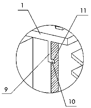
[0034] In addition, a clamping plate 9 is provided on the lower end surface of the upper cover plate 1 and the upper end surface of the lower cover plate 2, and the clamping plate 9 is L-shaped, see figure 2 , the clamping portion 10 of the clamping plate 9 faces outside the wire containing cavity 4 . Correspondingly, on the side of the left side plate 3...

Embodiment 2

[0044] This embodiment provides a high heat dissipation busway, including an upper cover 1, a lower cover 2, a left side 3 and a right side 3, an upper cover 1, a lower cover 2, a left side 3 and a right side The board 3 encloses a wire containing chamber 4, and a busbar 5 is installed in the wire containing chamber 4. Wherein, bolt holes are provided on the upper end faces and lower end faces of the left side plate 3 and the right side plate 3, and bolt holes are also provided at the corresponding positions on the upper cover plate 1 and the lower cover plate 2, which are stabilized by bolts during installation. connect.

[0045] In addition, a clamping plate 9 is provided on the lower end surface of the upper cover plate 1 and the upper end surface of the lower cover plate 2, and the clamping plate 9 is L-shaped, see figure 2 , the clamping portion 10 of the clamping plate 9 faces outside the wire containing cavity 4 . Correspondingly, on the side of the left side plate 3...

Embodiment 3

[0055] This embodiment provides a high heat dissipation busway, including an upper cover 1, a lower cover 2, a left side 3 and a right side 3, an upper cover 1, a lower cover 2, a left side 3 and a right side The board 3 encloses a wire containing chamber 4, and a busbar 5 is installed in the wire containing chamber 4. Wherein, bolt holes are provided on the upper end faces and lower end faces of the left side plate 3 and the right side plate 3, and bolt holes are also provided at the corresponding positions on the upper cover plate 1 and the lower cover plate 2, which are stabilized by bolts during installation. connect.

[0056] In addition, a clamping plate 9 is provided on the lower end surface of the upper cover plate 1 and the upper end surface of the lower cover plate 2, and the clamping plate 9 is L-shaped, see figure 2 , the clamping portion 10 of the clamping plate 9 faces outside the wire containing cavity 4 . Correspondingly, on the side of the left side plate 3...


PUM


Abstract

The invention discloses a high-cooling bus duct, and relates to the technical field of electric equipment. The high-cooling bus duct comprises an upper cover plate, a lower cover plate and a pair of side plates; the upper cover plate, the lower cover plate and the side plates define a wire accommodating cavity; a bus is mounted in the wire accommodating cavity; cooling fins are arranged on one sides, facing the exterior of the wire accommodating cavity, of the side plates; each cooling fin comprises a plurality of cooling sheets which are parallel to one another; an included angle between eachcooling fin and each side plate is an acute angle; a cooling groove is formed between every two adjacent cooling sheets on each side plate; and the cooling groove is located in a horizontal projection of any cooling sheet on each side plate. The invention further discloses a preparation method of the high-cooling bus duct. The strength of the bus duct is improved, and the high-temperature resistance of the bus duct is improved by 28-32%.

Description

technical field [0001] The invention relates to the technical field of electric equipment, in particular to a high heat dissipation bus duct and a preparation method thereof. Background technique [0002] With the emergence of modern engineering facilities and equipment, the power consumption of all walks of life is increasing rapidly, especially the emergence of many high-rise buildings and large factory buildings. The traditional cables used as power transmission wires can no longer meet the requirements in the current high-current transmission system. The parallel use of multi-channel cables has brought a lot of inconvenience to the on-site installation and construction connections. Bus ducts have increasingly replaced wires and cables in indoor low-voltage power transmission trunk line projects. [0003] Due to the compact structure of the busbar and the fact that the busbar will generate a lot of heat after working for a long time, the existing busway generally has a hi...

Claims


Application Information

Patent Timeline
Patent Type & Authority Applications(China)
IPC IPC(8): H02G5/06H02G5/10C08L63/00C08K13/06C08K9/06C08K3/22C08K5/5419C08J3/28
CPCC08J3/28C08J2363/00C08K3/22C08K5/5419C08K9/06C08K13/06C08K2003/2227C08K2201/011C08L2201/08H02G5/06H02G5/10C08L63/00
Inventor 李培成刘永欣耿政
Owner 辰亮科技信息服务(江苏)有限公司
Why Eureka
Try Eureka