Bus capacitor discharge control method of vehicle motor controller

A technology for motor controllers and busbar capacitors, applied in current collectors, battery circuit devices, electric vehicles, etc., can solve problems such as lack of good countermeasures, shortened life of power batteries, damage to power batteries, etc., to shorten the charge and discharge cycle, Optimized motor control, reliable discharge effect

Pending Publication Date: 2019-09-13
CRRC YONGJI ELECTRIC CO LTD
View PDF7 Cites 6 Cited by
  • Summary
  • Abstract
  • Description
  • Claims
  • Application Information

AI Technical Summary

Problems solved by technology

Once there is a fault in the active discharge circuit, the discharge control strategy will fail, and the discharge of the bus capacitor will be undertaken by the passive discharge circuit, and the discharge time will be extended; at the same time, when there are special circumstances (such as the car is on a long downhill, coasting in neutral), The drive motor is in the state of pumping power, causing the bus voltage to be higher than the normal voltage state (such as 600V) in the running state of the vehicle. The current discharge strategy has no good countermeasures for this, and it is all absorbed by the power battery, which may damage the power battery , shorten power battery life

Method used


Image

  • Bus capacitor discharge control method of vehicle motor controller
  • Bus capacitor discharge control method of vehicle motor controller
  • Bus capacitor discharge control method of vehicle motor controller

Examples


Embodiment Construction

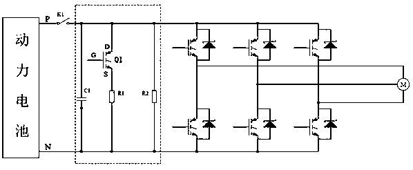
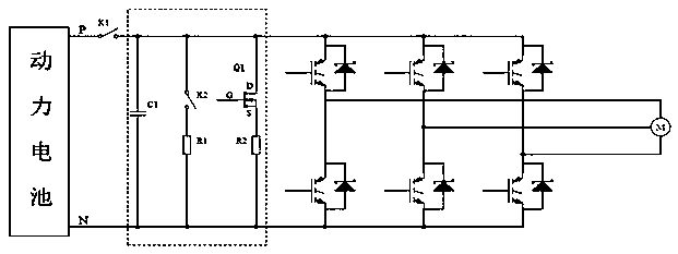
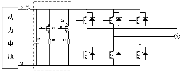
[0019] The method for controlling the discharge of the bus capacitor of the vehicle motor controller, the discharge circuit of the bus capacitor of the vehicle motor controller is composed of two active discharge circuits connected in parallel at both ends of the bus capacitor, and the active discharge circuit is composed of an active discharge resistor and a controllable discharge circuit The switches are connected in series; the controllable discharge switches of the two active discharge circuits are controlled by the processor in the motor controller MCU of the vehicle, and the control method is realized by the following steps:

[0020] 1) Detect the vehicle key switch signal. When the vehicle key switch is in the open state (parking state), control the controllable discharge switch of an active discharge circuit to close. Even if the active discharge circuit is turned on, the specified discharge time t After that (the discharge time t is determined according to the actual n...


PUM


Abstract

The invention relates to a bus capacitor discharge strategy for a vehicle motor controller, in particular to a bus capacitor discharge control method for a vehicle motor controller. The invention solves the defects and problems existing in the discharge strategy of a bus capacitor discharging circuit of an existing vehicle motor controller. The discharging circuit of the bus capacitor of the vehicle motor controller is composed of two active discharging circuits connected in parallel at the two ends of the bus capacitor, and each active discharging circuit is formed by connecting an active discharge resistor and a controllable release switch in series; and the controllable release switches of the two active discharging circuits are controlled by a processor in a motor controller MCU of thevehicle, and when a vehicle key switch is in an open state, the two active discharging circuits are controlled to be sequentially conducted; when the automobile is in a long-down slope, a neutral-gear sliding state or a motor fault state to cause the vehicle speed to be in a sudden change state, the two active discharging circuits are controlled to be sequentially conducted, so that the damage ofcomponents in the circuit caused by violent fluctuation of the bus voltage can be reduced or even avoided; and meanwhile, a power battery is protected.

Description

technical field [0001] The invention relates to a busbar capacitance discharge strategy of a motor controller for a vehicle, in particular to a control method for discharging the capacitor of a busbar of a motor controller for a vehicle. Background technique [0002] New energy vehicles work in a high-voltage environment. With the rapid development of new energy vehicles, people pay more and more attention to the high-voltage safety of new energy vehicles, and the high-voltage safety requirements of the electric drive system of new energy vehicles are also getting higher and higher. The bus capacitor is an important part of the MCU power circuit of the automotive motor controller. It and the automotive power battery provide a reliable and stable power supply for the power module, smooth the bus voltage, reduce the line inductance, and ensure the good operation of the drive motor. When the vehicle is running, the bus capacitor is always in a high voltage state (such as 540V)....

Claims


Application Information

Patent Timeline
Patent Type & Authority Applications(China)
IPC IPC(8): H02J7/00H02J7/14
CPCH02J7/1461H02J7/0029H02J7/0068
Inventor 范钱旺叶勇薛旭阳黑文洁孙晨阳
Owner CRRC YONGJI ELECTRIC CO LTD
Why Eureka
Try Eureka