Tubular motor assembly with hollow cup motor structure

A technology of motor structure and tubular motor, applied in the direction of electric components, electrical components, structural connections, etc., can solve the problems that the reduction ratio of the reducer cannot meet the demand, the limit of the motor output torque, the life limit of the whole machine, etc., to achieve the braking effect. Good, the response speed is improved, and the installation stability is high.

Pending Publication Date: 2019-09-13
HANGZHOU WISTAR MECHANICAL& ELECTRIC TECH CO LTD
View PDF11 Cites 4 Cited by
  • Summary
  • Abstract
  • Description
  • Claims
  • Application Information

AI Technical Summary

Problems solved by technology

There are many deficiencies in the existing tubular rare earth or ferrite motors, for example: 1. There is a rotor iron core, and the mass of the rotor iron core is large, so that the rotor has slow response speed, high energy consumption, and large vibration when starting and stopping. The damage to the components is serious, which limits the life of the whole machine; secondly, the rotor core will generate eddy currents in the magnetic field, which will cause the motor to heat up, consume high energy, and have low efficiency
2. The magnetic tile (permanent magnet) is fixed on the casing, and the magnetic tile (permanent magnet) must have a certain thickness. In the case of a certain external diameter of the motor, the external diameter of the motor rotor will be greatly restricted, thus The output torque of the motor is greatly limited
The above solution solves the problem that the reduction ratio of the reducer of the existing tubular motor cannot meet the demand to a certain extent, but this solution still has many shortcomings of ordinary rare earth or ferrite motors, and at the same time, this solution still has other shortcomings. For example, poor transmission stability, etc.

Method used


Image

  • Tubular motor assembly with hollow cup motor structure
  • Tubular motor assembly with hollow cup motor structure
  • Tubular motor assembly with hollow cup motor structure

Examples


Embodiment Construction

[0039] The present invention will be described in further detail below in conjunction with the accompanying drawings and specific embodiments.

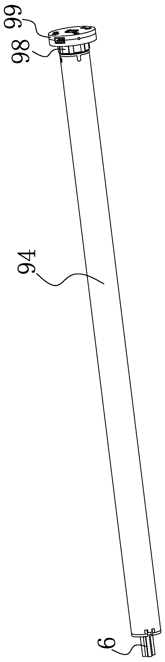
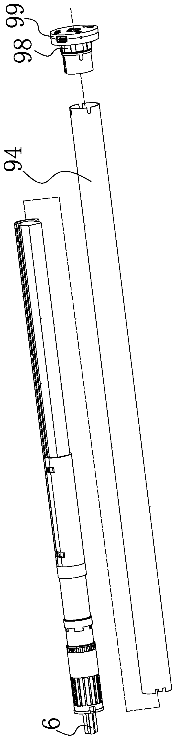
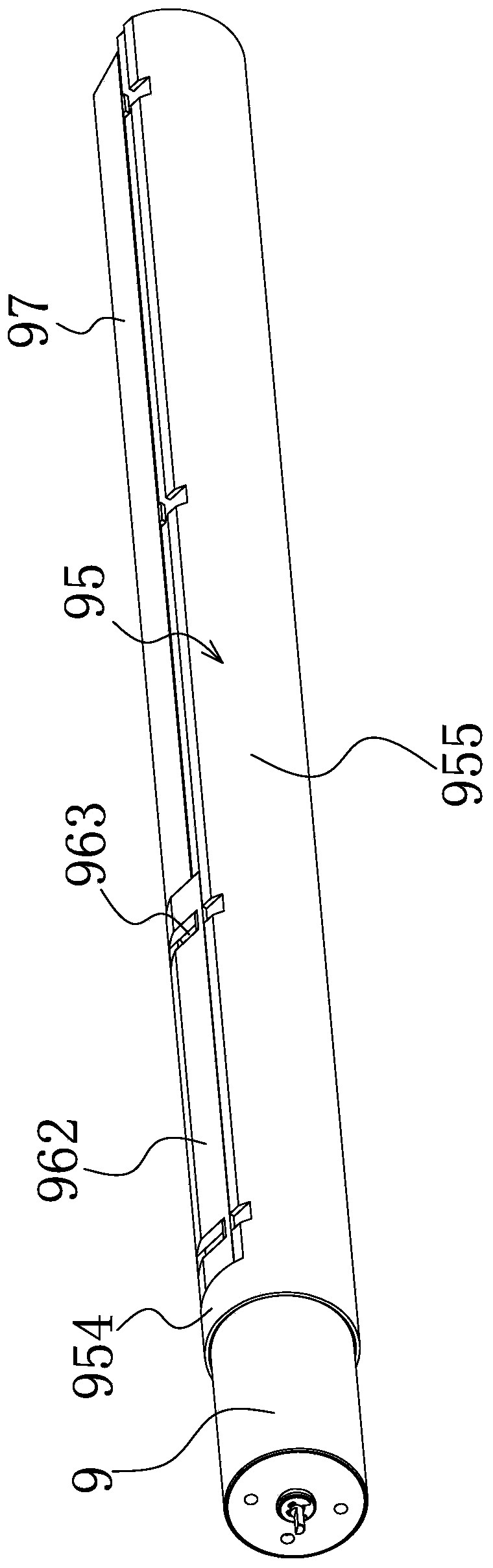
[0040] Such as Figure 1-5 As shown in and 7, the tubular motor assembly adopting the hollow cup motor structure includes a hollow steel pipe body 94, and the steel pipe body 94 is pierced with a motor body 9, and the motor body 9 is a hollow cup motor, wherein the motor body here 9 includes a motor housing 93, one end of the motor housing 93 has a carbon brush group 931 connected to the control circuit, the rotor frame 932 with the above-mentioned motor shaft 92 is rotated on the carbon brush group 931, and the motor shaft 92 is provided with The coreless coil 933 is provided with a permanent magnet 934 located in the circumferential inner side of the coreless coil 933 in the motor housing 93 , and the motor shaft 92 passes through the permanent magnet 934 and extends to the outside of the motor housing 93 . Preferably, one end of t...


PUM


Abstract

The invention relates to a tubular motor assembly with a hollow cup motor structure, and solves the problem that an existing tubular motor is insufficiently reasonable in design. The tubular motor assembly comprises a steel pipe body and a hollow cup motor; one end of a motor main body is inserted into a battery circuit board shell; a control circuit board and / or a power supply battery is arrangedin the battery circuit board shell; the other end of the motor main body is connected with a primary gear ring; a motor shaft of the motor main body is connected with a primary planetary gear assembly; the other end of the primary gear ring is connected with a secondary gear ring and a tertiary gear ring through a brake jacket; a primary planetary deceleration assembly is connected with a secondary planetary gear assembly through a brake structure; a tertiary planetary gear assembly is connected with an output shaft; and the other end, away from the output shaft, of the steel pipe body is connected with a cover body through a limiting ring. The tubular motor assembly has the advantages that a rotor iron core structure is cancelled; the hollow cup motor has no cogging effect; and no eddy current is generated, so that the response speed is greatly increased and the vibration is greatly weakened when a rotor is started and stopped, and the service life of the whole machine is prolonged.

Description

technical field [0001] The invention belongs to the technical field of motor equipment, and in particular relates to a tubular motor assembly adopting a hollow cup motor structure. Background technique [0002] With the rapid development of the electromechanical industry, motors have been widely used in our current lives. For example, tubular motors have the advantages of compact structure, large torque, and slow speed as driving devices. Therefore, tubular motors are increasingly used in Rolling shutter doors and windows, sunshade systems, projection screens and other products that complete the lifting movement electrically. Since the motor shaft of the tubular motor rotates too fast, a reducer is generally provided on the tubular motor for ease of use, so that the rotational speed of the output shaft meets the needs of normal use. Existing DC tubular motors are generally ordinary rare earth or ferrite motors, which have structural features such as rotor iron cores and mag...

Claims


Application Information

Patent Timeline
Patent Type & Authority Applications(China)
IPC IPC(8): H02K11/00H02K11/30H02K7/116H02K7/102
CPCH02K11/0094H02K11/30H02K7/116H02K7/102H02K2207/03H02K11/33
Inventor 孙旭东朱才龙
Owner HANGZHOU WISTAR MECHANICAL& ELECTRIC TECH CO LTD
Why Eureka
Try Eureka