
Agricultural punching machine

A mechanical and agricultural technology, applied in the field of agricultural planting equipment, can solve problems such as low efficiency, planting hole collapse, planting hole damage, etc., and achieve the effect of improving the drilling effect, convenient adjustment, and convenient drilling depth

Inactive Publication Date: 2019-09-17
邓福凤
View PDF0 Cites 0 Cited by
  • Summary
  • Abstract
  • Description
  • Claims
  • Application Information

AI Technical Summary

Problems solved by technology

[0003] In agricultural production, it is necessary to drill holes to make planting holes to facilitate subsequent sowing. The traditional punching device uses manual punching, which is inefficient. In addition, after the planting holes punched by the punching device, the punching rod is easy to bring out the soil, causing The planting hole collapsed, and the planting hole at the place was destroyed

Method used


Image

  • Agricultural punching machine
  • Agricultural punching machine
  • Agricultural punching machine

Examples


Embodiment 1

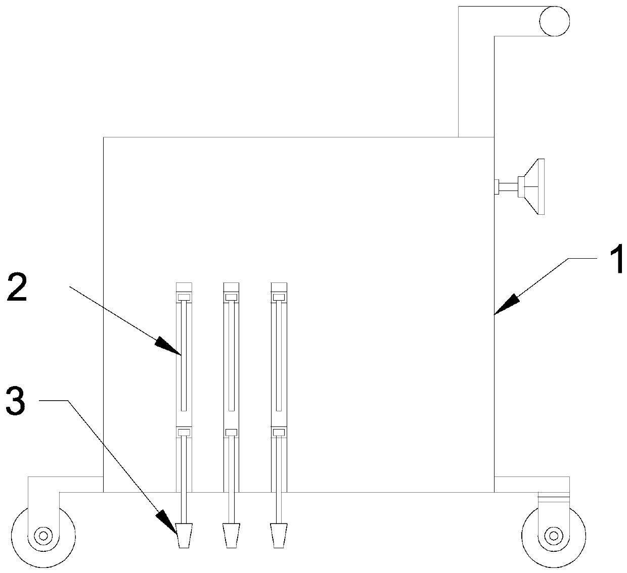
[0023] see Figure 1-6 , in an embodiment of the present invention, an agricultural punching machine includes a cart 1 and a punching rod 2; the front side of the cart 1 is provided with a punching rod 2, the punching rod 2 is a columnar rod, and the punching rod 2 Below is provided with shaping cylinder 3, and shaping cylinder 3 is the conical cylinder of upper and lower end openings, and the opening diameter of shaping cylinder 3 lower ends is larger than the diameter of punching rod 2 by 1 millimeter; The center of circle of the shaped tube 3 is located in the same vertical line, the punching rod 2 and the shaping tube 3 are respectively connected with a telescopic frame mechanism, and the telescopic frame mechanism drives the punching rod 2 and the shaping tube 3 to move toward each other or move backwards. Yes, when the punching rod 2 is punching, the punching rod 2 and the shaping cylinder 3 move toward each other, and the punching rod 2 passes through the shaping cylind...

Embodiment 2

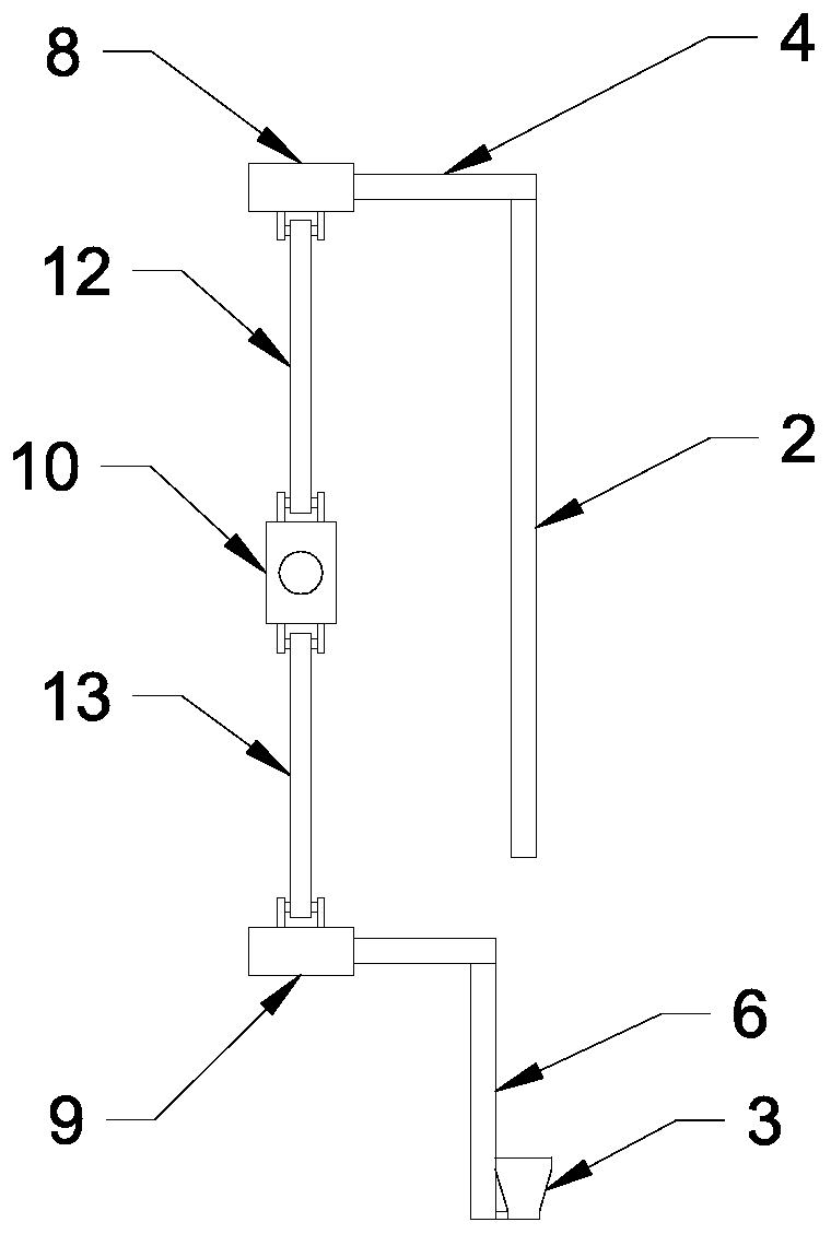
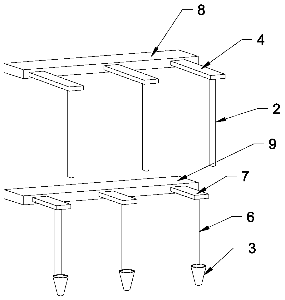
[0025] The difference between this embodiment and Embodiment 1 is that the telescopic frame mechanism includes an upper moving plate 8 and a lower moving plate 9 arranged symmetrically up and down, and the punching rod 2 is fixedly connected with the upper moving plate 8 through the upper extending plate 4 , plastic The shaped cylinder 3 is connected with a lower extension plate 7 through a vertical rod 6, and the lower extension plate 7 is fixedly connected with the lower moving plate 9; a moving block 10 is arranged between the upper moving plate 8 and the lower moving plate 9, and the moving block 10 is connected with the upper moving plate 8 through the upper connecting rod 12 arranged symmetrically, and the upper connecting rod 12 is respectively hinged with the moving block 10 and the upper moving plate 8, and the moving block 10 is connected with the lower moving plate 9 through the lower connecting rod 13, and the lower connecting rod 13 are respectively hinged with the...


PUM


Abstract

The invention discloses an agricultural punching machine which comprises a cart and a punching rod. The punching rod is arranged at the front side of the cart, a shaping cylinder is arranged below the punching rod, and the punching rod and the shaping cylinder are connected with a stretchable frame mechanism for driving the punching rod and the shaping cylinder to move in a face-to-face mode or a back-to-back mode. Due to the punching rod and the shaping cylinder connected with the stretchable frame mechanism, the punching rod and the shaping cylinder move in the face-to-face mode or the back-to-back mode, during punching, the shaping cylinder can scrape away soil stuck to the punching rod, meanwhile, when the shaping cylinder continues to move downwards, extrusion and shaping are performed on the inner wall of a planting hole, the inner wall of the planting hole are punned and fixed, and the punching effect is improved; by arranging a lifting connecting rod, a sliding block and a two-way lead screw, the height of the punching rod is adjusted, and the punching depth can be adjusted conveniently.

Description

technical field [0001] The invention relates to the field of agricultural planting equipment, in particular to an agricultural drilling machine. Background technique [0002] Agricultural machinery is generally classified by use. Most of the machinery is specially designed and manufactured according to the characteristics of agriculture and the special requirements of various operations, such as soil tillage machinery, planting and fertilization machinery, plant protection machinery, crop harvesting machinery, animal husbandry machinery and agricultural product processing machinery. The other part of agricultural machinery is common to other industries and can be directly selected according to the characteristics and needs of agriculture, such as agricultural power machinery, water pumps in farmland drainage and irrigation machinery, etc.; or these machines can be designed as agricultural variants according to the characteristics and needs of agriculture, such as agricultura...

Claims


Application Information

Patent Timeline
Patent Type & Authority Applications(China)
IPC IPC(8): A01C5/04
CPCA01C5/04
Inventor 邓福凤
Owner 邓福凤
Learn More