Laser thinning method and laser machine

A laser thinning and laser machine technology, applied in laser welding equipment, metal processing equipment, welding equipment, etc., can solve problems such as uneven surface, and achieve the effect of high flatness and consistent cutting volume

Active Publication Date: 2021-08-03
SHENZHEN H TECH CO LTD
View PDF7 Cites 0 Cited by
  • Summary
  • Abstract
  • Description
  • Claims
  • Application Information

AI Technical Summary

Problems solved by technology

[0003] The main purpose of the present invention is to provide a laser thinning method, aiming at solving the problem of surface unevenness easily caused when the workpiece to be processed is thinned

Method used


Image

  • Laser thinning method and laser machine
  • Laser thinning method and laser machine
  • Laser thinning method and laser machine

Examples


no. 1 example

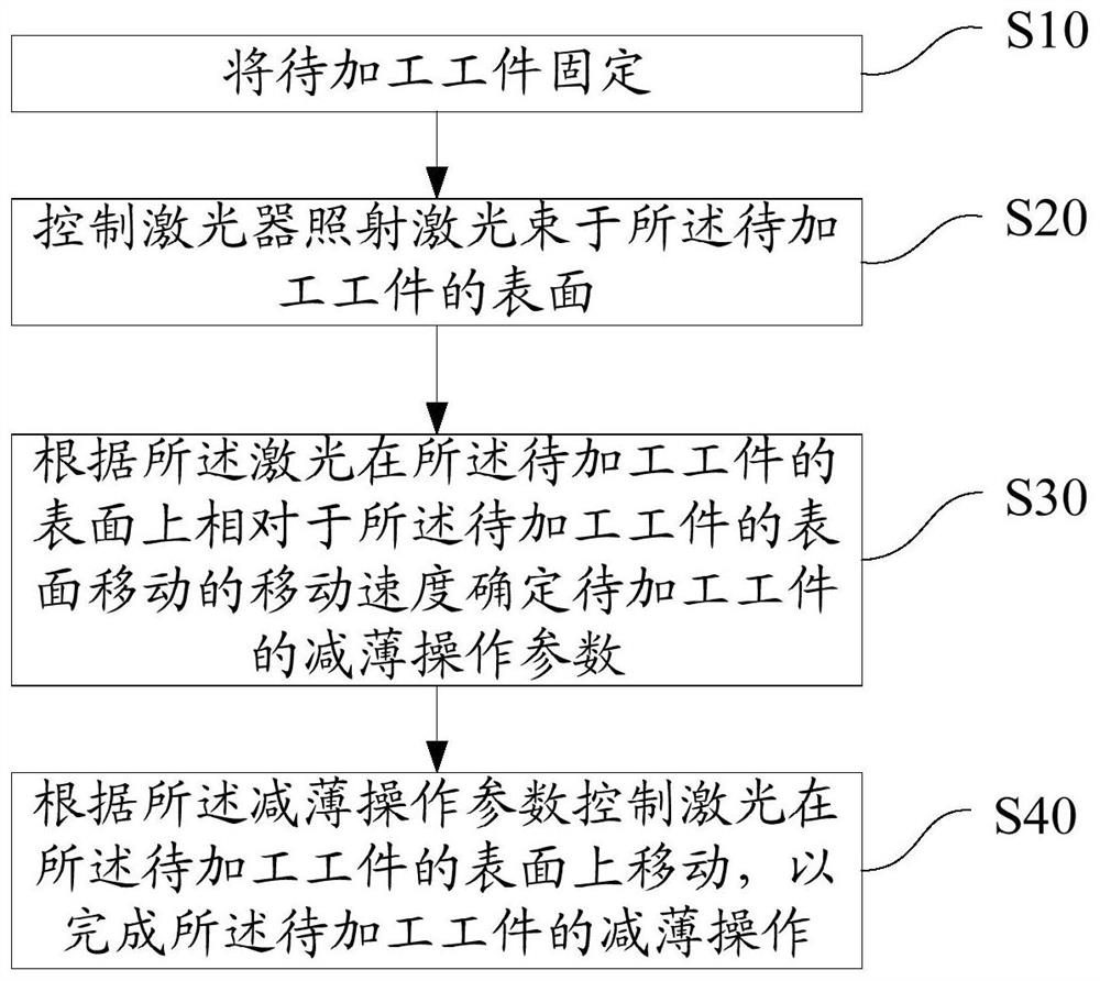
[0079] refer to figure 2 , figure 2 As the first embodiment of the laser thinning method of the present invention, the laser thinning method includes the following steps:

[0080] Step S10, fixing the workpiece to be processed.

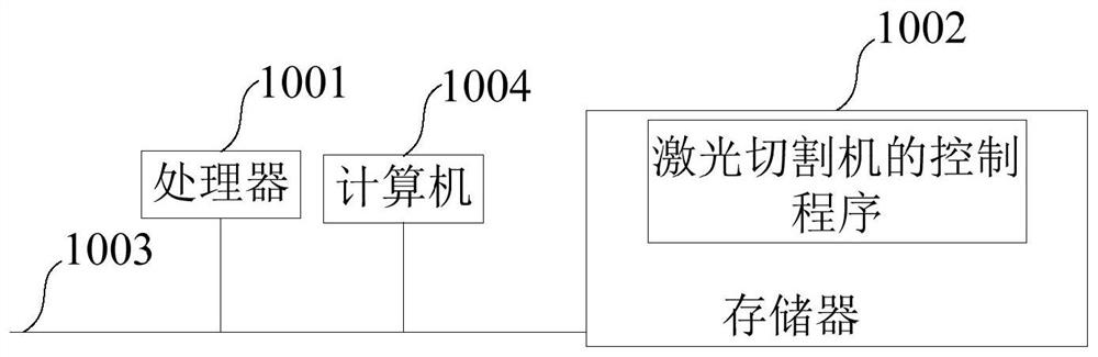
[0081] In the present invention, a laser cutting machine refers to a laser cutting machine with a rotating table, and the laser cutting machine is equipped with a rotating table for clamping a workpiece to be processed and driving it to rotate. When the laser machine is running, the laser machine clamps the workpiece to be processed on the rotating table through the built-in fixture so that the workpiece to be processed is fixed for thinning, and the required clamping can be provided according to the weight of the workpiece to be processed force.

[0082] Step S20, controlling the laser to irradiate the surface of the workpiece to be processed.

[0083] Specifically, according to the thickness of the workpiece to be processed, the distance betwe...


PUM


Abstract

The invention discloses a laser thinning method. The laser thinning method comprises the following steps: fixing the workpiece to be processed; controlling the laser to irradiate the surface of the workpiece to be processed; The moving speed on the surface of the workpiece relative to the surface of the workpiece to be processed determines the thinning operation parameters of the workpiece to be processed; according to the thinning operation parameters, the laser is controlled to move on the surface of the workpiece to be processed to complete the workpiece to be processed. Thinning operations for machining workpieces. The invention also discloses a laser machine. The invention ensures that the surface smoothness of the workpiece to be processed is better after the thinning process.

Description

technical field [0001] The invention relates to the technical field of laser processing, in particular to a laser thinning method and a laser machine. Background technique [0002] In the past, the surface thinning process of the product generally used a grinding wheel to grind the surface of the workpiece to be processed, but the processing efficiency of this method was relatively slow. At present, in order to improve the efficiency of product thinning, when thinning a workpiece, a laser is usually used to thin the surface of the workpiece to be processed. However, because the surface of the product is generally irregular, when the laser is used to thin the surface of the workpiece to be processed, the speed of the laser moving along the plane is different from that of the curved surface. When the moving speed of the laser is too fast, it is easy to cause part of the path to be reduced. The lack of thinning will cause the unevenness of the plane after thinning, and its fla...

Claims


Application Information

Patent Timeline
Patent Type & Authority Patents(China)
IPC IPC(8): B23K26/38B23K26/70
CPCB23K26/38B23K26/702
Inventor 岳国汉
Owner SHENZHEN H TECH CO LTD
Why Eureka
Try Eureka