Tool clamp

A tooling fixture and clamping technology, applied in the field of tooling fixtures, can solve the problems of low welding efficiency, complex shape, heavy weight, etc., and achieve the effect of simple structure setting, less material input, and low production cost

Inactive Publication Date: 2019-09-17
SANY HEAVY EQUIP
View PDF2 Cites 1 Cited by
  • Summary
  • Abstract
  • Description
  • Claims
  • Application Information

AI Technical Summary

Problems solved by technology

[0003] Usually, the assembly and welding of the vehicle frame 1' is realized by manually adding hoisting equipment, especially when the rear tailstock 60' and the rear longitudinal beam 40' are assembled and welded, because the shape of the rear tailstock 60' is complic

Method used


Image

  • Tool clamp
  • Tool clamp
  • Tool clamp

Examples


Embodiment Construction

[0061] In order to understand the above-mentioned purpose, features and advantages of the present invention more clearly, the present invention will be further described in detail below in conjunction with the accompanying drawings and specific embodiments. It should be noted that, in the case of no conflict, the embodiments of the present application and the features in the embodiments can be combined with each other.

[0062] In the following description, many specific details are set forth in order to fully understand the present invention. However, the present invention can also be implemented in other ways different from those described here. Therefore, the protection scope of the present invention is not limited by the specific details disclosed below. EXAMPLE LIMITATIONS.

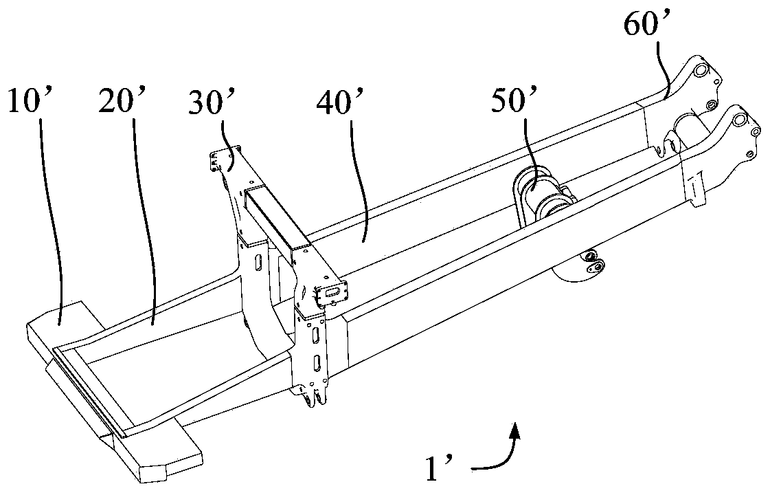
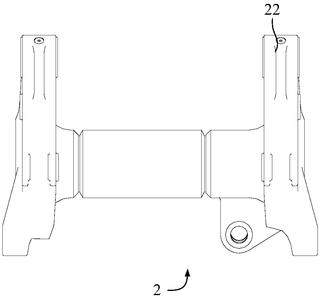
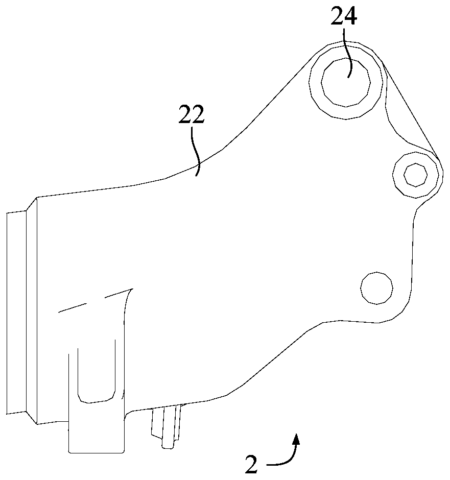
[0063] Refer below Figure 2 to Figure 19 The work clamp 1 according to some embodiments of the present invention is described.

[0064] Such as Figure 2 to Figure 9 As shown, the embodiment of t...


PUM


Abstract

The invention provides a tool clamp. The tool clamp is used for mounting and clamping a rear tailstock of a frame, and a connecting hole is formed in the rear tailstock. The tool clamp comprises a body, a first driving part and a second driving part, wherein the body is provided with a connecting shaft, the connecting shaft penetrates through the connecting hole, the first driving part is arranged on the body and is used for driving the rear tailstock to rotate around the axis of the connecting shaft, and the second driving part is arranged on the body and is used for driving the rear tailstock to move in the axial direction of the connecting shaft. According to the tool clamp, the structure of the tool clamp is reasonably arranged, so that under the situation that the assembling size of the connecting hole and a carriage is not changed, the assembling size of the rear tailstock relative to a rear longitudinal beam can be adjusted in the height direction and the left-right direction according to a specific actual situation, namely, the assembling size of the rear tailstock relative to the rear longitudinal beam can be adjusted in the plurality of directions, a plurality of angles and a plurality of dimensions by utilizing the tool clamp, a precise and reliable assembly structure foundation is provided for subsequent splicing and welding, the labor intensity of workers is reduced, the assembly welding efficiency of the frame is improved, and the production cost is reduced.

Description

technical field [0001] The invention relates to the technical field of mechanical processing, in particular to a tooling fixture. Background technique [0002] At present, the structural form of the mining dump truck frame 1' is as follows figure 1 Shown: From front to back, it is assembled and welded by bumper 10', front longitudinal beam 20', ring beam 30', rear longitudinal beam 40', torque tube 50' and rear tailstock 60'. Before assembly welding, it is necessary to adjust the ring beam 30' to the preset position, then place the bumper 10', front longitudinal beam 20', rear longitudinal beam 40' and torque tube 50' to a reasonable position, and finally adjust the rear tailstock 60' to achieve tack welding. [0003] Usually, the assembly and welding of the vehicle frame 1' is realized by manually adding hoisting equipment, especially when the rear tailstock 60' and the rear longitudinal beam 40' are assembled and welded, because the shape of the rear tailstock 60' is com...

Claims


Application Information

Patent Timeline
IPC IPC(8): B23K37/04
CPCB23K37/0443
Inventor 黄志怀梁海莎邓辉
Owner SANY HEAVY EQUIP
Why Eureka
Try Eureka