Integrated type power plant indirect air cooling tower

An air-cooling tower and integrated technology, which is applied in the field of ventilation and cooling towers in thermal power plants, can solve the problems of increasing the head of the circulating water pump and power consumption, increasing the radial size of the air-cooling tower, and increasing the civil construction investment of the air-cooling tower, so as to improve the cost economy , Promote the improvement of environmental quality and the effect of reducing pollutant emissions

Inactive Publication Date: 2019-09-17
CHNA ENERGY INVESTMENT CORP LTD +3
View PDF6 Cites 3 Cited by
  • Summary
  • Abstract
  • Description
  • Claims
  • Application Information

AI Technical Summary

Problems solved by technology

If the processing capacity of the heat exchanger is increased by increasing the number of heat exchangers along the circumference of the air-cooling tower, the radial dimension of the air-cooling tower will be greatly increased, the civil construction investment of the air-cooling tower will be increased, and the height and diameter of the air-cooling tower will be reduced. ratio, which reduces the economy of the cost; if the heat exchanger’s processing capacity is increased by increasing the height of the heat exchanger, the flow velocity and water side resistance inside the heat exchanger will be limited by the height of the heat exchanger and the diameter of the pipe. Entering the rapid growth range, the head and power consumption of circulating water pumps will increase significantly

Method used


Image

  • Integrated type power plant indirect air cooling tower
  • Integrated type power plant indirect air cooling tower
  • Integrated type power plant indirect air cooling tower

Examples


Embodiment Construction

[0040] In order to make the object, technical solution and advantages of the present invention clearer, the present invention will be described in further detail below in conjunction with specific embodiments and with reference to the accompanying drawings. Wherein the same components are denoted by the same reference numerals. It should be noted that the words "front", "rear", "left", "right", "upper" and "lower" used in the following description refer to directions in the drawings. The terms "inner" and "outer" are used to refer to directions toward or away from, respectively, the geometric center of a particular component.

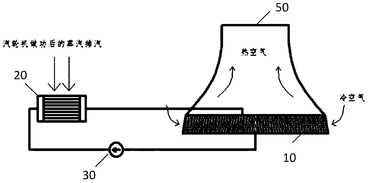
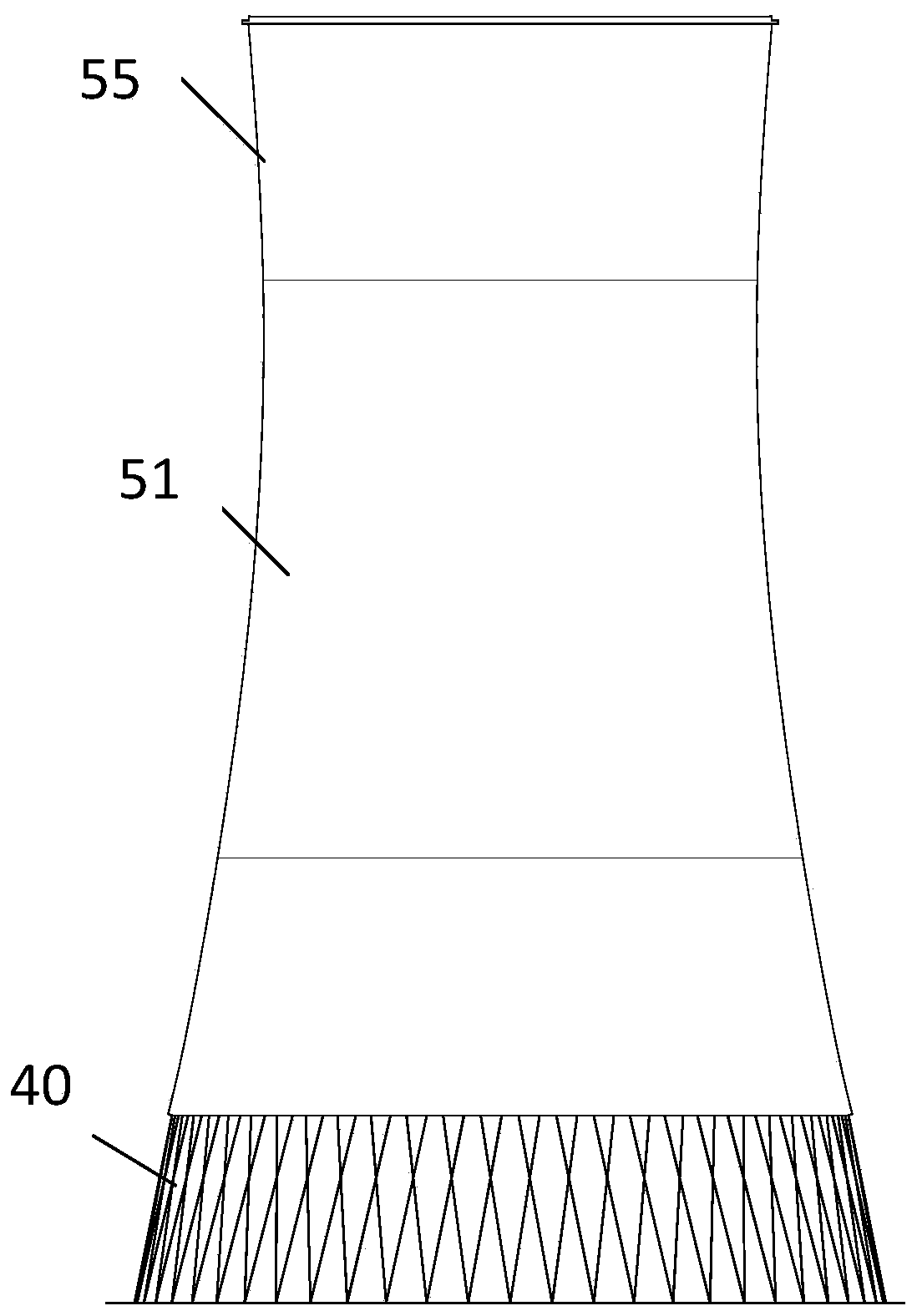
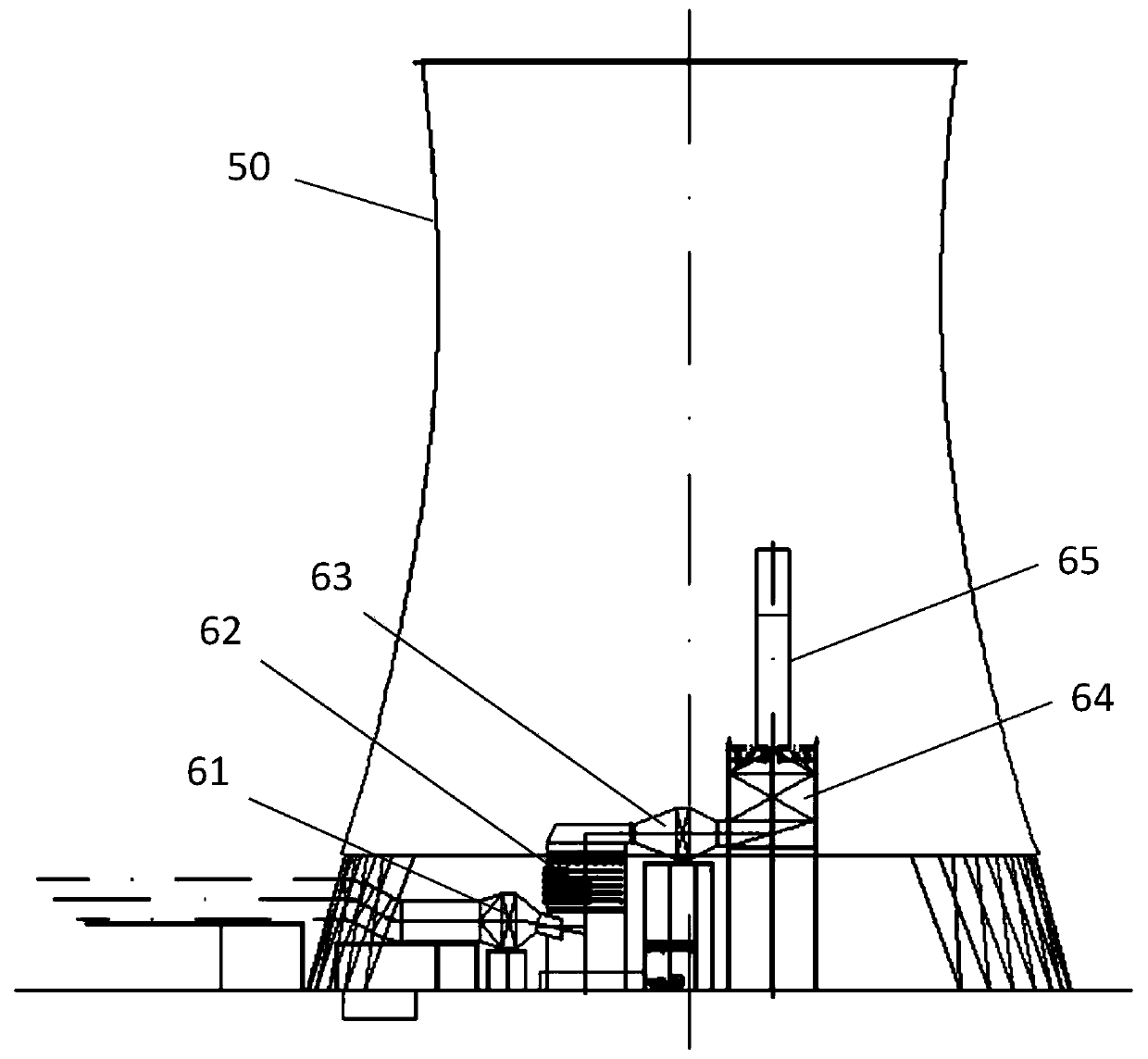
[0041] figure 1 It is the usage state diagram of the integrated indirect air cooling tower of the power plant adopted in the specific embodiment of the present invention. figure 2 for figure 1 Schematic diagram of the tower tube of the integrated power plant indirect air cooling tower shown. Figure 3a for figure 1 The schematic diagram of the int...


PUM


Abstract

The invention discloses an integrated type power plant indirect air cooling tower. The integrated type power plant indirect air cooling tower comprises a tower cylinder, a flue gas denitrification device, a flue gas waste heat exchange device, a heat exchange device and a steam turbine power device, wherein a gas inlet and a gas outlet are formed in the tower cylinder, at least a set of flue gas treatment system is arranged in the tower cylinder, each flue gas treatment system comprises a desulfurizing absorption tower, a clean flue gas water extraction device, a dust removal device and a chimney, which are sequentially arranged from the gas inlet to the gas outlet and communicate with one another through a pipeline, the flue gas denitrification device and the flue gas waste heat exchange device are arranged between a boiler furnace and the gas inlet, the heat exchange device is arranged outside the tower cylinder, the heat exchange device is distributed in the circumferential direction of the tower cylinder and extended in the height direction of the tower cylinder, the heat exchange device comprises a water inlet pipe and a water outlet pipe, a lift pump is arranged on the water inlet pipe or the water outlet pipe, the steam turbine power device comprises a steam condenser, and an inlet end and an outlet end of the steam condenser communicate with the heat exchange device respectively through the water inlet pipe and the water outlet pipe so as to form a circulating pipeline. The integrated type power plant indirect air cooling tower is low in construction cost and good in use performance.

Description

technical field [0001] The invention relates to the technical field of ventilation cooling towers in thermal power plants, and more specifically, relates to an integrated indirect air cooling tower for power plants. Background technique [0002] The thermal power generating set is an important equipment of the thermal power plant. The thermal power generation unit is a unit that uses coal as fuel to heat the water in the boiler to increase its temperature, and then uses a certain pressure of steam to drive the steam turbine to generate electricity. Air cooling is currently the most widely used circulating cooling method for steam turbines. The indirect air cooling tower used for cooling the end of the thermal power plant unit has a stronger ability to resist high temperature environments and strong winds, and has stronger adaptability. [0003] For units above 1000MW, the flue gas treatment capacity is large, and the types and contents of pollutants are large, which puts fo...

Claims


Application Information

Patent Timeline
Patent Type & Authority Applications(China)
IPC IPC(8): F28C1/14F23J15/04F23J15/02
CPCF23J15/025F23J15/04F23J2215/20F23J2217/10F28C1/14
Inventor 王树民李志明赵永红任全在赵志刚张成锐朱大宏张大勇赵弦刘林佘长超张明玉皇甫建飞董斌琦
Owner CHNA ENERGY INVESTMENT CORP LTD
Why Eureka
Try Eureka