Refrigerant piping and refrigeration cycle apparatus

A refrigeration cycle and refrigerant technology, applied in refrigeration and liquefaction, refrigerators, refrigeration components, etc., can solve the problems of deterioration of performance coefficient, increase of pressure loss of refrigerant, difficulty in securing space for muffler, etc., and reduce pulsation Abnormal noise and the effect of suppressing the loading space

Inactive Publication Date: 2019-09-17
DENSO CORP
View PDF9 Cites 1 Cited by
  • Summary
  • Abstract
  • Description
  • Claims
  • Application Information

AI Technical Summary

Problems solved by technology

Therefore, the muffler may interfere with other mounted components in the engine room, making it difficult to secure a mounting space for the muffler.
[0011] In addition, the pressure loss of the refrigerant in the anechoic chamber and the resonance chamber increases, so the coefficient of performance (so-called COP) of the cycle may deteriorate.

Method used


Image

  • Refrigerant piping and refrigeration cycle apparatus
  • Refrigerant piping and refrigeration cycle apparatus
  • Refrigerant piping and refrigeration cycle apparatus

Examples


no. 1 approach

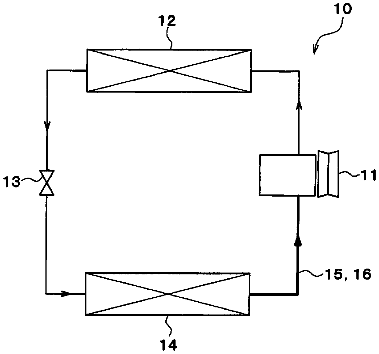
[0028] figure 1 The illustrated refrigeration cycle device 10 is applied to a vehicle air conditioner. The refrigeration cycle device 10 is a vapor compression refrigerator including a compressor 11 , a condenser 12 , an expansion valve 13 , and an evaporator 14 . In the refrigeration cycle apparatus 10 of the present embodiment, a freon-based refrigerant is used as a refrigerant, and a subcritical refrigeration cycle is configured in which the pressure of the refrigerant on the high-pressure side does not exceed the critical pressure of the refrigerant.

[0029] The compressor 11, the condenser 12, the expansion valve 13, and the evaporator 14 are arranged in series with each other in the flow of the refrigerant.

[0030] The compressor 11 sucks in the refrigerant of the refrigeration cycle device 10 and compresses and discharges the refrigerant. The compressor 11 is a belt-driven compressor or an electric compressor. The belt-driven compressor is a compressor driven by tr...

no. 2 approach

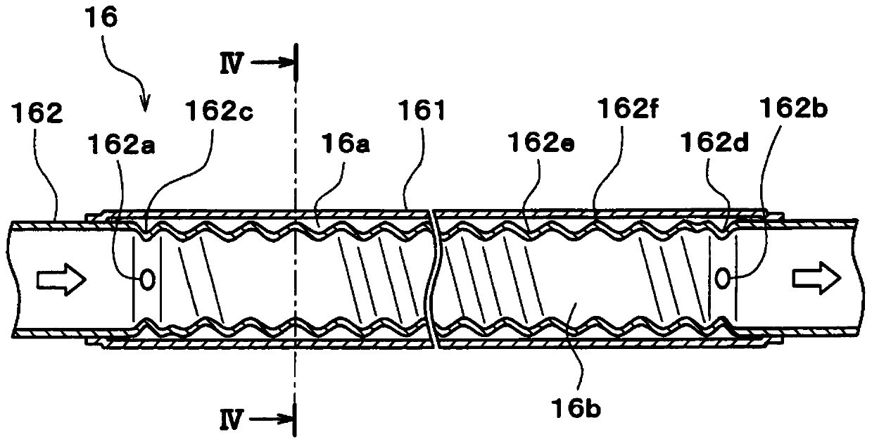
[0071] In the above-mentioned embodiment, the diverging communication hole 162a and the converging communication hole 162b are formed at both ends of the inner tube 162 in the longitudinal direction, but in this embodiment, as Figure 5 As shown, in addition to the branch flow communication hole 162a and the flow connection communication hole 162b, a plurality of intermediate communication holes 162g are formed in the middle portion in the longitudinal direction of the inner tube 162 .

[0072] As a result, the frequency of branching and merging of the refrigerant between the inner and outer flow passages 16a and the inner flow passage 16b increases, so that pulsation can be effectively reduced.

[0073] In the present embodiment, an intermediate communication hole 162g is arranged between the branch communication hole 162a and the confluence communication hole 162b. Thereby, it is possible to reliably perform the branching and merging of refrigerants.

no. 3 approach

[0075] In the above-mentioned embodiment, the double pipe 16 extends straight, but in this embodiment, as Image 6 As shown, the bilayer tube 16 buckles.

[0076] The double pipe 16 has a plurality of bent portions 163 in order to avoid interference with the engine, various devices, and the main body in the engine room.

[0077] A method for forming the bent portion 163 will be briefly described. First, the inner tube 162 formed with the inlet groove portion 162c, the outlet groove portion 162d, and the helical groove portion 162e is inserted into the outer tube 161 . Next, both tubes 161 and 162 are bent at predetermined locations while keeping the inner tube 162 inside the outer tube 161 . Thus, the bent portion 163 is formed.

[0078] When the curved portion 163 is formed in this way, the circular cross section of the outer tube 161 is deformed into a flat shape earlier than that of the inner tube 162 . Therefore, if Figure 7 As shown, the inner wall of the outer tube...


PUM


Abstract

A refrigerant piping according to a first aspect of the present disclosure is provided with dividing parts (162a, 162g), a first flow passage part (16a), a second flow passage part (16b), and merging parts (162b, 162g). The dividing parts divide the flow of a refrigerant at a refrigerant outlet-side of an evaporator (14) of a refrigeration cycle (10) and at a refrigerant inlet-side of a compressor (11) of the refrigeration cycle. In the first flow passage part and the second flow passage part, the refrigerants divided in the dividing part flow in parallel to each other. The refrigerants flowing through the first flow passage part and the second flow passage part merge at the merging part. The first flow passage part and the second flow passage part have flow passage lengths different from each other. According to the refrigerant piping, since the flow passage lengths of the first flow passage part and the second flow passage part are different from each other, a phase difference is generated between the pulsations of the refrigerant flow of the first flow passage part and the refrigerant flow of the second flow passage part, and an effect in which the pulsations cancel each other occurs. As a result, pulsation noise can be reduced. Also, the pulsation noise from the compressor can be reduced while maximally suppressing an increase in mounting space or pressure loss.

Description

[0001] Cross-reference of related applications [0002] This application is based on Japanese Patent Application No. 2017-20265 filed on February 7, 2017, the contents of which are cited here. technical field [0003] The present invention relates to a refrigerant pipe used in a refrigeration cycle and a refrigeration cycle device provided with the refrigerant pipe. Background technique [0004] Patent Documents 1 and 2 describe a noise reduction device used in a refrigeration cycle. This noise reduction device reduces the drive sound and pulsation sound of the compressor transmitted to the refrigerant of the refrigeration cycle, and is arranged in the middle of the low-pressure refrigerant piping on the suction side of the compressor. [0005] The noise reduction device of Patent Document 1 is called a bar type. Specifically, the noise reduction device of Patent Document 1 is a noise reduction device in which a noise reduction chamber is formed in a swollen shape between ...

Claims


Application Information

Patent Timeline
IPC IPC(8): F25B41/00F04B39/00F04B39/12
CPCF04B39/00F04B39/12F25B2500/12B60H1/00571B60H2001/006F25B41/40B60H1/00899F04C23/008F25B30/02F25B41/42F16L9/18F16L55/04F16L11/22
Inventor 佐藤秀一
Owner DENSO CORP
Why Eureka
Try Eureka